Configuration, Dc input and data, Mounting – Studio Technologies 5130 2013 User Manual
Page 9: Rs-485 address id
Model 5130 User Guide
Issue 5, July 2013
Studio Technologies, Inc.
Page 9
Model 5130
Party-Line Interface Module
DC Input and Data
A 4-position header, located adjacent to
the audio input and output headers, is
used to connect DC power and RS-485
data to the Model 5130. For details on
appropriate mating connectors refer to
Appendix B located at the end of this
document.
A source of nominal 12 volts DC, with an
acceptable range of 10 to 18, is required
for Model 5130 operation. The maximum
current is 800 milliamperes at 12 volts DC.
For remote control operation an RS-485
data bus connection from a compatible
Studio Technologies’ remote access mod-
ule is required. Most applications will only
have the DC power connections imple-
mented so these two pins will typically
remain unconnected. Refer to Figure 4
for details.
Mounting
The Model 5130 is intended for mount-
ing into an installation-specific enclosure
or rack panel. Refer to Appendix A for the
unit’s dimensions and mounting screw
locations. Please contact the factory to
discuss mounting options.
Configuration
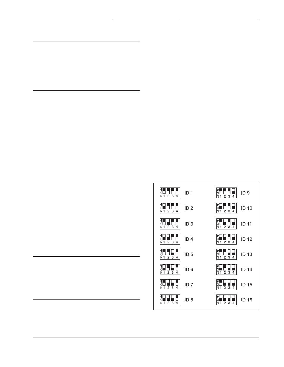
RS-485 Address ID
One configuration setting must be per-
formed for applications that implement
remote control of Model 5130 functions. Up
to sixteen Model 5100-Series modules can
“share” an RS-485 data bus but each must
have a unique address ID. Selecting the
device’s address ID involves setting four
DIP switches. Refer to Figure 5 for details.
Figure 5. RS-485 Address ID Settings
Pin Number
Function
1
– DC (Common)
2
+ DC (10-18 volts)
3
+ Data (RS-485)
4
– Data (RS-485)
Figure 4. DC Input/Data
Pin Number
Function
1
Common/Shield
2
+ CH1
3
– CH1
4
+ CH2
5
– CH2
Figure 3. Audio Outputs