Model 770 – Studio Technologies 770 User Manual
Page 31
Model 770 User Guide
Issue 1, October 1997
Studio Technologies, Inc.
Page 31
Model 770
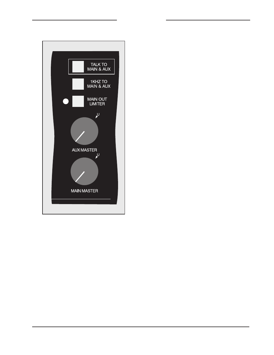
1kHz to Main and AUX
A 1kHz tone signal can be connected to
the main and AUX buses, serving as a
reference signal for local and remote use.
A push-button switch selects its status;
when the switch is in the in position tone is
connected. The tone level is factory set to
precisely match the Model 770s internal
operating level. When the tone is con-
nected to the main and AUX buses, the
main and AUX master level controls can
be adjusted to give 0 level on the meter.
Talk to Main and AUX
A button allows audio from the gooseneck
microphone to be connected to the main
and AUX buses, creating a talk back
function for cueing, slating, and setup use.
The monitor output and IFB monitor out-
put both are automatically muted when-
ever the talk to main and AUX function is
active. Note that the voice audio signal will
be added (summed) with whatever signals
are also present on the buses.
IFB Section
The IFB section is located on the left side
of the Model 770s front panel.
Program and Interrupt Bus Operation
Probably the most complicated part of
the Model 770 is how the IFB section
creates the IFB signal. Actually, it really
quite simple, but may take users a few
moments of quiet meditation before the
mental light bulb goes on! Once some-
one gets the chance to use the controls
and experiment routing signals, all should
become clear.
The first topic that must be covered is how
the Model 770 defines program audio and
interrupt audio. Program audio is a signal
that connects to the IFB output during
normal operation. Interrupt audio is a
signal whose mere presence causes it to
be connected to the IFB output, as well as
causing muting or dimming (attenuating)
of the program audio. Internal to the
Model 770s IFB section are two audio
buses (highways); program and inter-
rupt. The program audio bus has a mute/
dim circuit associated with it. The interrupt
bus has a special voice detection circuit
associated with it. Commonly known as
a VOX circuit, it generates a logic signal
Figure 12. Detail of front panel showing
master output section