Studio Technologies 40 User Manual
Page 10
Model 40 User Guide
Issue 1, July 1994
Studio Technologies, Inc.
Page 11
If one or both audio sources is monaural
several installation options are available:
• The mono signal is wired to both the
left and right inputs, thus sending
two channels of audio to the talent
amplifiers. This installation is simple,
but prevents the rapid connect of a
stereo source should the need arise.
• The mono source is connected to the
left input only. As both the Model 35
and Model 38 Talent Amplifiers contain
a monaural switch, talent amplifier
users can select to hear the signal in
both channels. This has the downside
of possibly confusing users who don’t
know to press the mono button.
• Our preferred installation has the left
and right inputs connected to points
on a patch bay. The mono source
would be connected to the “normal”
connections on both the left and right
patch points. This would feed the
mono signal to both the left and right
inputs, while giving the ability to
quickly “patch in” a stereo source.
Talent Amplifier Outputs
The Model 40 contains two talent amplifier
output groups which are designated Group
A and Group B. Each group will support up
to four Model 35 or Model 38 Talent Am-
plifiers in any combination. Two male XLR-
type connectors are provided on the Model
40’s back panel for connecting to the
output groups.
For best performance, use low-capaci-
tance shielded microphone-type cable to
distribute the output groups. If you have a
choice, select cable with the heaviest wire
gauge commonly available. This will re-
duce voltage drop when using long cable
runs. Refer to the Technical Notes section
for additional information.
The simplest installation would use micro-
phone cables to connect the Model 40 to
the first talent amplifier in each group; the
loop through connector on the first talent
amps sending the signal on to the next.
For convenience, you may want to wire
your facility to allow easy access to the
output groups at all locations where talent
amplifiers might be used. Talent amplifiers
connect to an output group in parallel, so
the connectors on the distribution panels
or mult boxes must be wired in parallel.
Warning: Do not connect talent ampli-
fier output signals to anything but Studio
Technologies’ talent amplifiers. Some
audio equipment may be damaged by
the +23Vdc contained on pin 2 of the
talent amplifier output group connectors.
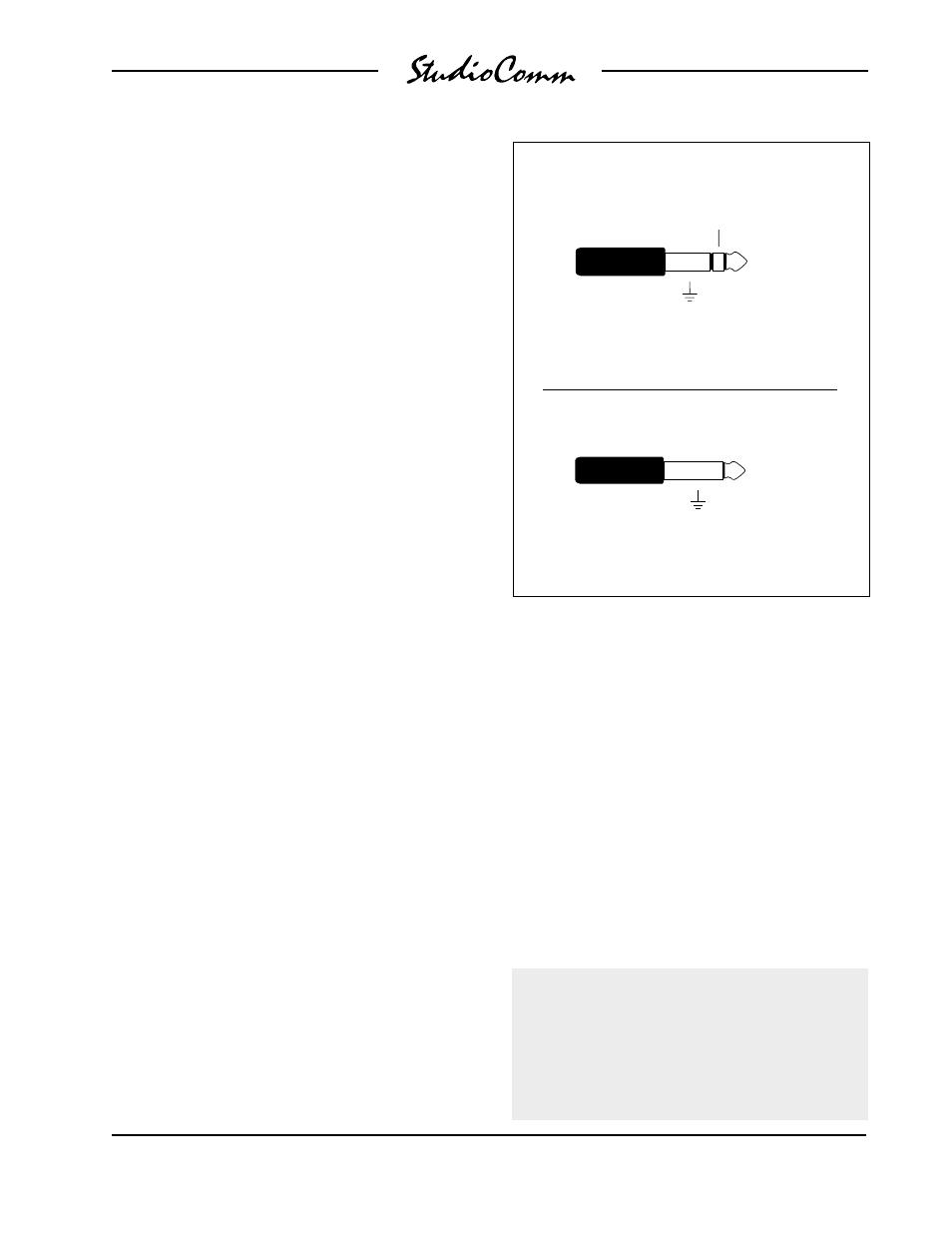
Balanced Input
Connection
Sleeve
(Shield)
Ring (–)
(Switchcraft No. 297, Neutrik NP3C, or equivalent)
Unbalanced Input
Connection
Sleeve
(Shield)
Tip ( + )
(Switchcraft No. 280, Neutrik NP2C, or equivalent)
Tip ( + )