Configuration, Operation, Level meters – Studio Technologies 5121 User Manual
Page 9: Mounting, Rs-485 address
Model 5121 User Guide
Issue 3, October 2014
Studio Technologies, Inc.
Page 9
Model 5121
Line/IFB Output Module
The line outputs were designed for general-
purpose use and can drive balanced or
unbalanced loads. The IFB output is intend-
ed to directly support listen-only beltpacks
such as the Models 32A, 33A, and 34 Talent
Amplifiers from Studio Technologies.
Level Meters
The two audio level meters on the Model
5121 are calibrated differently from typical
“VU” meter scales. Their “steps” are
labeled in reference to the nominal level
of both the line and IFB outputs. For 5121S
modules the green “0” LED corresponds
to a +4 dBu line output and a –10 dBu
IFB output audio level. For 5121E modules
the “0” LED corresponds to 0 dBu and
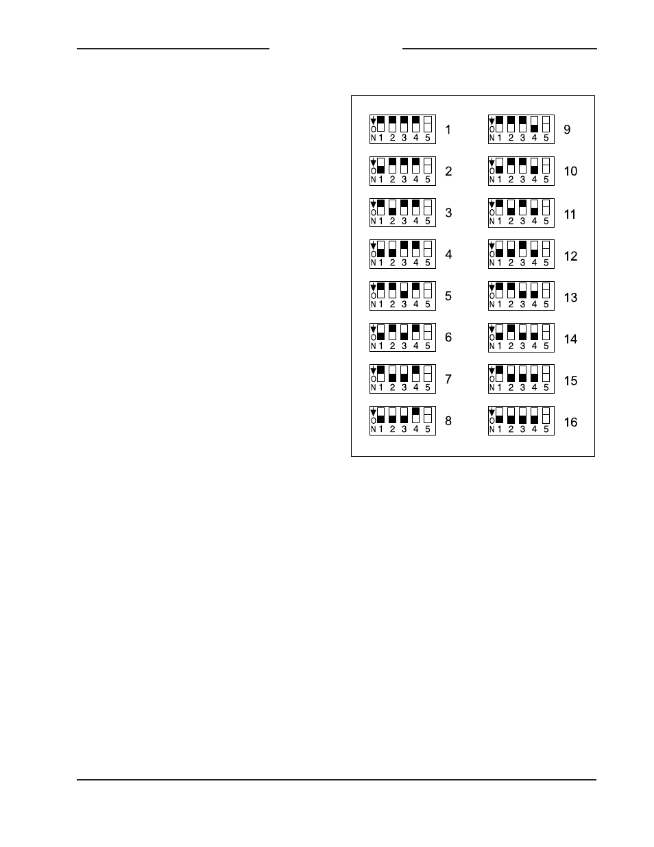
Figure 4. RS-485 Address Settings
Mounting
The Model 5121 is intended for mount-
ing into an installation-specific enclosure
or rack panel. Refer to Appendix B for the
unit’s dimensions and mounting screw loca-
tions. Please contact the factory to discuss
mounting options.
Configuration
RS-485 Address
A data bus address must be configured for
applications that implement remote control
of Model 5121 functions. While up to 16
Model 5100-Series modules can “share” the
RS-485 data bus, each module must have
a unique address. Selecting the device’s
address involves setting four configuration
switches located on one side of the module.
The switches are a “piano key” type with
their up position being defined as off and
their down position defined as on. Note that
switch 5 of the switch assembly is not used
by the Model 5121. Refer to Figure 4 for
details.
Operation
The Model 5121 is designed for continuous
operation with no adjustment or mainte-
nance required. On the input side, main-
taining the correct levels coming from the
analog or digital audio sources is very im-
portant. This will ensure proper signal levels
are being presented to users and maintain
optimal audio fidelity. The audio meters and
IFB output voltage status LED function (“DC
PIN 2”) will assist users in confirming that
correct operation is taking place. In addi-
tion, the under-voltage shutdown function
will help to protect the IFB output circuitry
should a fault condition be detected.