Introduction – Studio Technologies 42A 2008 User Manual
Page 5
Model 42A User Guide
Issue 2, February 2008
Studio Technologies, Inc.
Page 5
Introduction
The Model 42A is designed to create
broadcast-standard IFB circuits from line-
level audio sources. The unit’s primary
application is to interface analog outputs
associated with digital matrix intercom
systems with broadcast IFB user devices.
The Model 42A provides four independent
IFB circuits. For convenience, the four
circuits can be connected by way of eight
3-pin male XLR-type connectors; four of
which are located on the back panel and
four on the front. Each IFB circuit provides
DC power and two analog audio signals to
support the connected IFB user devices.
The Model 42A’s audio quality is excellent;
little hiss, hum, or other artifacts are pres-
ent. To ensure optimal operation, the unit
provides resources for visually and audibly
monitoring the audio output signals. In
addition, the DC output voltage is moni-
tored for over-current and short-circuit
conditions.
Installation of the Model 42A is very simple.
Audio input connections are made using
a 25-pin D-subminiature connector. The
IFB output circuits interface using standard
3-pin XLR-type connectors. The compact,
one-rack-space package is constructed
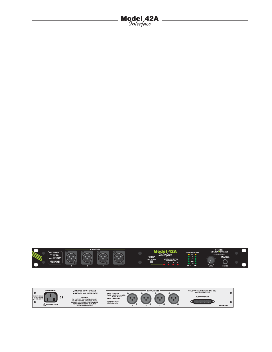
Model 42A Back Panel
Model 42A Front Panel
using heavy-gauge steel components. The
unit’s mains power input can range from
100 to 230 volts, 50/60 hertz. This “univer-
sal input” ensures correct operation virtu-
ally anywhere in the world.
There may be persons not familiar with
the term IFB. That’s not unreasonable
as it’s a somewhat obscure acronym for
interruptible foldback. On its own, the term
foldback is an alternate way of describ-
ing a cue or monitor function. Adding
“interruptible” before it means that the
cue source can be temporarily replaced
with an audio signal originating from a
producer, director, or other production
personnel. IFB circuits are often used in
the broadcast industry for talent cueing
applications, both in studio and field set-
tings. Both “dry” and “wet” IFB circuits
can be deployed and their characteristics
are worth reviewing. The term “dry” IFB
typically refers to a transformer-balanced
line-level audio circuit with a nominal level
in the range of 0 to +8 dBu. This is es-
sentially a standard audio circuit that is
commonly used to interconnect audio
equipment. The term “wet” IFB refers to
a circuit that combines DC power and
one or two channels of analog audio. The
nominal level of the DC power source is