Dometic 3400 User Manual
Page 6
6
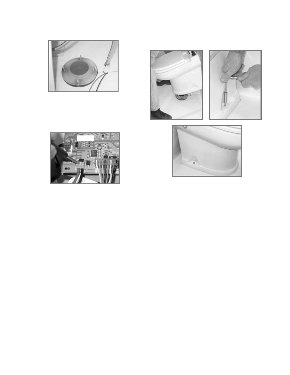
STEP 19: Set the toilet in place (fig. 19) and secure to
floor with the #14x2-1/2 inch long lag bolts (fig. 20). Install
decorative bolt caps by pushing them onto bolt heads
(fig. 21).
STEP 20: Place the rear access cover on the back of the
toilet. Press down firmly to seat the fastening strips.
STEP 21: Turn on electrical power and water to toilet.
Lift flush handle and fill toilet bowl with water. Wait one
hour, then inspect the floor around and under the rear of
the toilet for leaks or dampness.
If no leaks are present, toilet is ready for operation.
STEP 17: Insert the
positive (+) 12 VDC wire into
position 1 of the green terminal block and tighten the
screw securely. Insert the
negative (-) 12 VDC wire into
position 2 of the green terminal block and tighten the
screw securely (fig. 18).
Fig. 18
STEP 18:
REMOVE RED CAP FROM MIDDLE
OF FLANGE ADAPTER BEFORE FINAL TOILET
INSTALLATION.
IMPORTANT – DO NOT ATTEMPT TO SLIDE THE
TOILET OVER THE FLANGE ADAPTER. THE
TOILET MUST BE SET DOWN OVER THE ADAPT-
ER TO PREVENT POSSIBLE DAMAGE.
Fig. 21
Fig. 20
Fig. 19
STEP 16: With toilet close to floor flange, connect flex-
ible water supply hose to the water line fitting (fig. 17).
Fig. 17