Ii. installation overview – SP Controls PixiePlus User Manual
Page 5
II. Installation Overview
The PixiePlus ships with:
- 1 PixiePlus Circuit Board
- 7 White Plastic Button Inserts
- 1 Cable Assembly consisting of:
1 Plastic Cable Assembly Block
1 RS232/IR transmitter module (PXE-EMIT-232/IR)
1 6VDC Regulated Power Supply
Double-Sided Tape (attached to Block)
- IR Emitter Cable Anchors
- 2 Bezels (ivory and white)
- 1 3-position Captive Screw Connector for power/signal out from PixiePlus
- Instruction Manual
- Quick Start Guide
- Mounting Screws
- Paper Clip (for setting to IR-learning mode)
Required and Optional parts and accessories (not included)
- 1 3-conductor Cable (Required)
- 1 Leviton Decora™ wall plate (Required. Match to bezel color.)
- 1 Single-Gang Back Box (Optional. SP Controls recommends using a grounded
back box)
- Additional RS232/IR transmitter for control of additional display devices (Optional,
requires PXE-PGM-TOOL for RS232)
- PixiePlus programming tool (PXE-PGM-TOOL) for configuring the PixiePlus with
RS232 codes or realtime scheduling events
- PixiePlus Real-Time Clock (PXE-DCM-RTC): Allows the PixiePlus to perform
scheduled events, such as locking or powering devices off.
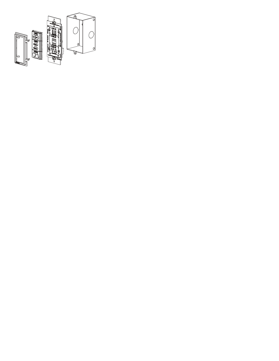
- Bezel Inserts Circuit Board Single-Gang Wall Box (not included)
NOTE: The PXE-EMIT-232/IR will not work with the PXE-DCM Pixie, nor can it be
used in combination with the PXE-EMIT.
3
Bezel
Single-Gang Wall Box
(not included)
Circuit Board
Inserts