SoundTraxx LC Series Owners Manual User Manual
Page 18
LC SERIES DIGITAL SOUND DECODER OWNER’S MANUAL
18
required in order for the DSD-LC to accept the new data (See the
LC Series Decoder Technical
Reference for details). Since most command stations that support extended addressing will au-
tomatically generate the correct protocol, simply follow their instructions for setting the extended
address.
Once the extended address is stored in CV 17 and 18, bit 5 of CV 29 must be set to 1 so the
decoder will recognize the extended address format. Otherwise, the decoder will continue to
respond only to its primary address. See the next section, Configuring the Decoder.
Step 2: Configuring the Decoder
The next CV you will want to change is CV 29, Decoder Configuration Byte. CV 29 is one of
those complicated bit variables mentioned earlier and is used in conjunction with other CVs to
set a multitude of decoder characteristics including:
Locomotive Direction - Causes the decoder to invert direction commands so that the locomo-
tive runs in reverse when it receives a command to move forward and vice-versa. This operating
mode is most useful for setting up diesel engines that ran with the long hood section forward.
However, it is also useful for electronically correcting installations where the motor wires were
accidentally reversed and avoids tearing apart the locomotive a second time.
Speed Step Mode Selection - As it is a digital system, the DSD-LC splits the throttle voltage over
its minimum and maximum range into discrete speed steps. The DSD-LC can be configured so
there are 14, 28 or 128 individual speed steps. The largest number of steps will give the smooth-
est throttle response. Be aware that not all DCC systems have the ability to control 28 or 128
speed steps and your choice will depend upon the capabilities of your command station.
Speed Table - Sets the decoder to use speed tables specified by CV 25 (see “Configuring the
Throttle”, page 19).
Primary or Extended Address - Sets the decoder to recognize its primary address in CV 1 or
extended address in CV 17:18 (see “Configuring the Address”, above).
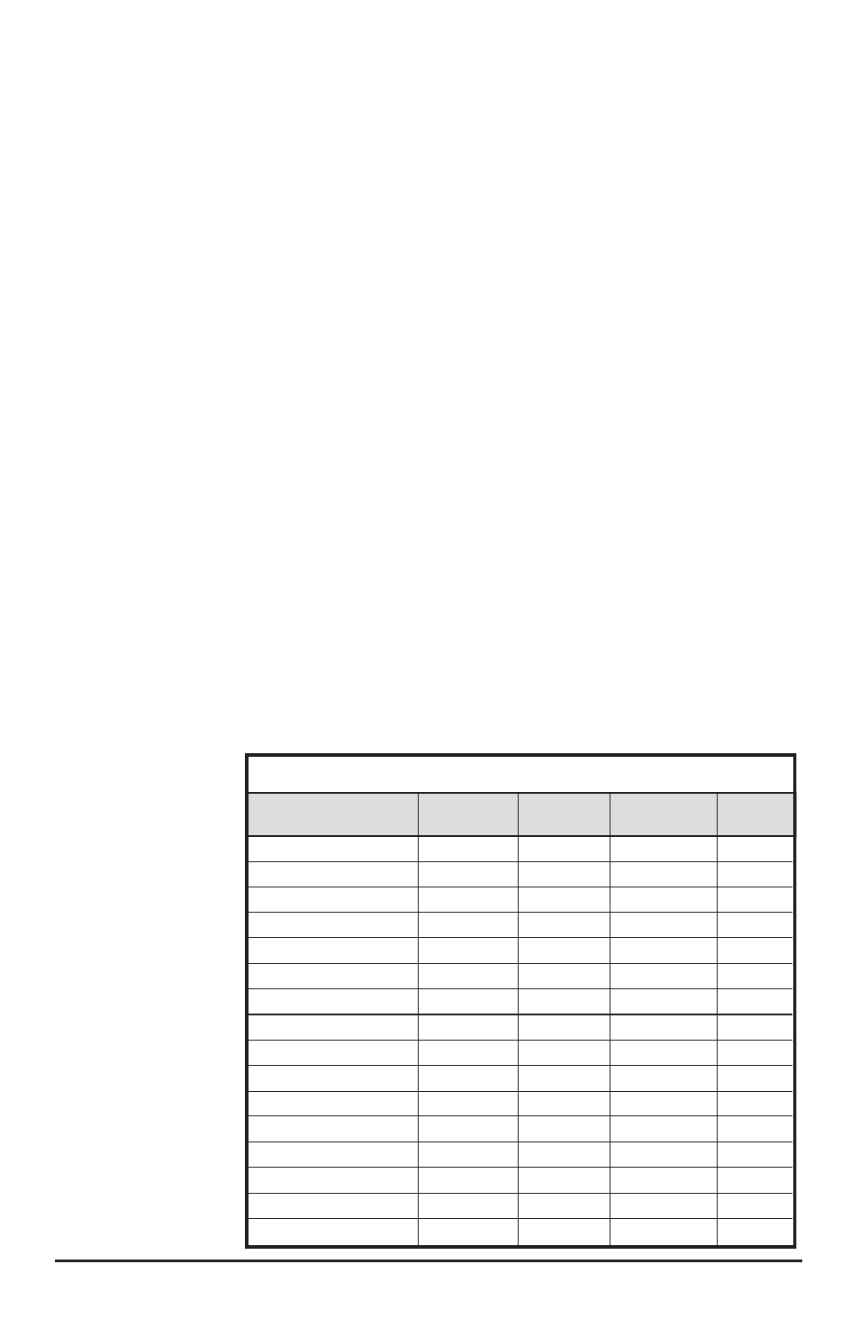
To assist the novice
user, we have
created Table A
that lists the correct
value for CV 29
to get the desired
operating modes.
Simply find the
row that has the
modes you want
and program CV 29
with the listed value.
The advanced user
should refer to the
DSD-LC Technical
Reference for more
details. Remember,
table values are
in decimal. If your
command station
uses Hexadecimal,
you will need to
convert the value
shown using
Appendix A.
Primary (CV1)
Primary (CV1)
Primary (CV1)
Primary (CV1)
Primary (CV1)
Primary (CV1)
Primary (CV1)
Primary (CV1)
Extended (CV17:18)
Extended (CV17:18)
Extended (CV17:18)
Extended (CV17:18)
Extended (CV17:18)
Extended (CV17:18)
Extended (CV17:18)
Extended (CV17:18)
Address Type
14
14
28/128
28/128
14
14
28/128
28/128
14
14
28/128
28/128
14
14
28/128
28/128
Speed
Steps
Normal
Reversed
Normal
Reversed
Normal
Reversed
Normal
Reversed
Normal
Reversed
Normal
Reversed
Normal
Reversed
Normal
Reversed
Locomotive
Direction
0
1
2
3
16
17
18
19
32
33
34
35
48
49
50
51
CV 29
Value
Use Speed
Tables?
No
No
No
No
Yes
Yes
Yes
Yes
No
No
No
No
Yes
Yes
Yes
Yes
Table A. Quick-Reference Table for CV29 Values