SONOSAX SX-S User Manual
Page 9
403. Brown Cable
404. 1
405. PFL-BUS-left
406. Connected to pin No 1 OP-7
407. Red Cable
408. 2
409. MASTER-BUS-right
410. Connected to pin No 1 OP-3
411. Orange Cable
412. 3
413. PFL-BUS-right
414. Connected to pin No 7 OP-7
415. Yellow Cable
416. 4
417. Auxiliary BUS
418. Connected to cursor Aux
potentiometer
419. Green Cable
420. 5
421. PFL Control-CDE (sense)
422. Connected to point R-6/R-5/collector
of Q1
423. Blue Cable
424. 6
425. MASTER-BUS-left
426. Connected to pin No 7 OP-3
427.
428.7.3 Optional
429. External Slate MIC for the Mixer's operator
430. To make the external slate Mic operational you will need to solder in R-7=15kOhms (R-5=49.9) and C-11=22pF remove R-10 on the extension module operator board.
Unsolder the internal mic on Connectors J-10 & J-11.
431. Then connect J-12 to the Bantam jack. Make sure that Jumper 2 is in position 2,3.
432. NOTE: The internal Slate Mic is deactivated by this procedure.
433. SX-S10 only: Remove the unused wire on the Bantam connector.
434.
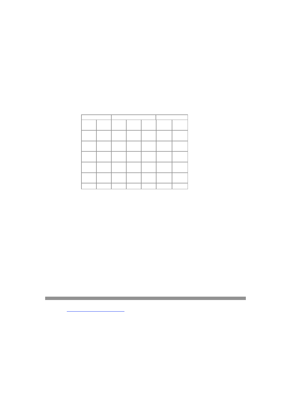
435.7.4 Y Cables for Boom Operator with tbk mic transmitter.
436. Click here for DIAGRAMof "Y" Cable
437. Internal connections of the Boom-Box (022260)
438. Click here for BOOM BOX Wiring Diagram
439. 860162
440. 860179
441. 860141
442. Pin
No
443.
444.
Ca
ble
445. Pin
No
446.
Ca
ble
447. Pin
448.
449.
450.
451.
452. 1
453.
Wh
ite
454. Tip
455.
Whi
te
456.
457.
458.
459. 2
460.
Wh
ite
461.
Rin
g
462.
Re
d
463. 1
464.
GN
D
465.
Bla
ck
466. 3
467.
Wh
ite
468.
GN
D
469.
GN
D
470. 3
471.
Wh
ite
472.
Bla
ck
473. 4
474.
475.
476.
477. 2
478.
Re
d
479.
Bla
ck
480. 5
481.
482.
483.
484.
485.
486.
487. 6
488.
489.
490.
491. 922110 External cable between SX-S extension module and SX-S extension box
492. Click here for MALE and FEMALE Socket Wiring
493.
494. Pin No
495. Pair No
496. Cable
497. Designation
498. 12
499. 4
500. Shield
501. GND
502. 11
503. 4
504. White
505. -12V
506. 10
507. 4
508. Yellow
509. +12V
510. 9
511. 3
512. Orange
513. Guest
514. 8
515. 3
516. White
517. Roll
518. 7
519. 3
520. Shield
521. 12V micro
522. 6
523. 2
524. Red
525. Right from Ext.
Box
526. 5
527. 2
528. White
529. Left from Ext.
Box
530. 4
531. 2
532. Shield
533. GND from Ext.
Box
534. 3
535. 1
536. Brown
537. Right to Ext.
Box
538. 2
539. 1
540. White
541. Left to Ext. Box
542. 1
543. 1
544. Shield
545. GND to Ext.
Box
546.
547. RETURN TO TABLE OF CONTENTS
548.
549.
550.
8.
FOUR CHANNEL MATRIX MODULE
551.
552. The four-channel matrix provides four outputs and four tape returns to accomodate 4-track recorders while still allowing a normal stereo or two-track mix.
553. Connections to the 4-track device is made through a 10 pin LEMO connector and Lemo to XLR adaptor cable.
554.
555.8.1 Channel assign Switches:
556. The first 9 rows of switches select which Input (1 through 9) is directed to which output (A through D). Switch up is off, switch down is selected. The signal is taken from
the channel after the fader and is still available on the Left & Right mix bus.
557. For example: To direct channel 1 to Output C, Switch 1-C would be down.
558. To direct channel 3 to output B, Switch 3-B would be down.
559.