524 motorized control valve drawing – Smithco Spray Star 2000D (sn 200D088 – 200D127) Parts & Service Manual User Manual
Page 70
68
Accessories
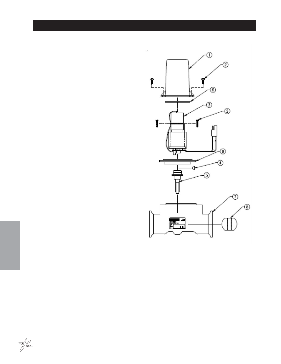
16-524 MOTORIZED CONTROL VALVE DRAWING
WHEN SERVICING VALVE:
Replace valve body with ISO-Body Kit if valve has
been leaking internally.
Replace motor assembly if the motor will not run.
Before reassembling valve, remove the coupler
shaft from the valve body. Apply Loctite to coupler
shaft and woodruff key. Place the coupler shaft (Ref
5) and the woodruff key (Ref 4) onto the motor
shaft. Plug motor into the valve connector coming
from Sprayer Control Console. Check that the mo-
tor rotates in both directions. Motor must stop
when coupler shaft CAM releases printed circuit
board button.
When reassembling valve, grease both sealing
surfaces of coupler shaft. Insert coupler shaft into
Iso-flange and be sure seal properly seats on shaft.
Install motor on valve body and apply silicon seal-
ant to mounting holes. Reassemble remaining
items as shown in parts diagram.
REF#
PART#
DESCRIPTION
QUANTITY
1
16-870
Valve Cover
1
2*
16-524-01
#6 Self Tapping Screw
3
/
4
" Long
6
3
16-875
Motor Assembly
1
4*
16-957
Woodruff Key
1
5*
16-524-02
Coupler Shaft
1
6*
16-897
Seal Tetraseal
1
7*
16-524-06
Valve Body Assembly 1"
1
8*
16-956
Butterfly
1
9*
16-524-04
Isolation Flange Assembly
1
*
16-524-05
1" Valve ISO-Body Kit
- Spray Star 2000D (sn 200D128 – Current) Parts & Service Manual Spray Star 2000D (sn 200D036 – 200D087) Parts & Service Manual Spray Star 2000 (sn 200G083 – 200G127) Parts & Service Manual Spray Star 2000 (sn 200G001 – 200G035) Parts & Service Manual Spray Star 2000 (sn 200G036 – 200G082) Parts & Service Manual Spray Star 2000 (sn 200G128 – Current) Parts & Service Manual