Introduction, Features, What’s in the box? installation diagram – Smart Avi VCT-400 User Manual
Page 2
Introduction
The VCT400 allows transmission of high definition
video signals over a standard CAT-5 UTP cable over
distances of up to 1000 ft.
Features
Uses easy to install, inexpensive CAT5.
Output reaches up to 1,000 feet.
Resolutions up to 1900x1200.
300 MHz Bandwidth.
Sends high-resolution VGA signals from
one source to up to 4 devices.
Compatible with VGA, XGA, Sun, MAC and SGI
signals.
Sync Format / Polarity Preservation.
High ground loop immunity.
Built-in lightning, power surge and transient
protection.
Designated trimmer in the remote unit to
compensate for cable length.
Compact Metal Case Enclosure.
Remote Units come with Buffered Outputs.
External power supply.
What’s in the box?
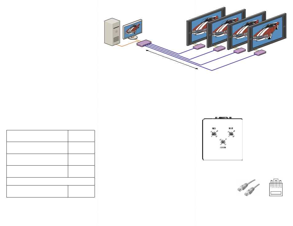
Installation Diagram
VCT Receiver Installation Diagram
Connecting The Transmitter
1. Connect the output of the computer video card to the
video input of the transmitter using the included male
to male video cable.
2. Connect local monitor to the VGA out of the
transmitter.
3. In the back of the unit connect the CAT5 cable that
will connect to the receiver unit.
4. Connect the power supply.
*NOTE: You can not use RS232 and IR at the same time or Audio.
Connecting The Receiver
1. Connect CAT5 cable (coming from the transmitter) to
the back of the receiver.
2. Connect monitors to the VGA out connectors on the
front of the receiver.
3. Connect the power supply.
Description
Part Number
4 port VCA UXGA
VCA-TX400
5VDC 1A Power Supply
PS-5D1A-US
VGA cable Male to Female
CC-VGAMM-06
Optional Equipment
VCAT-100-RX Receiver Unit
VCT-100-RX
Adjusting and Fine Tuning the Signal
Preparing & Connecting System CAT5 Cable
Following is the wiring standard for terminating CAT 5
cable using RJ-45 connector:
Pair 1
Pins 1 & 2
Pair 2
Pins 3 & 6
Pair 3
Pins 4 & 5
Pair 4
Pins 7 & 8
Connectors:
RJ-45
Capacitance:
14 pf/ft (46.2 pf/m)
Conductor Gauge:
24 AWG
Impedance:
100 +/- 15 ohms
4 - Pair
In order to fine tune the signal,
adjust the individual dials
one at a time starting with
GREEN, then BLUE and lastly
RED. As you turn the dials you
will notice the colors slightly
change as you increase or
decrease the strength.
VCT Transmitter Installation Diagram
Up to 1,000 ft.
VCA-TX400
Transmitter
VCT-100-RX
Transmitter’s