Introduction, Features, Installation diagram – Smart Avi DVX-PLUS User Manual
Page 2
Introduction
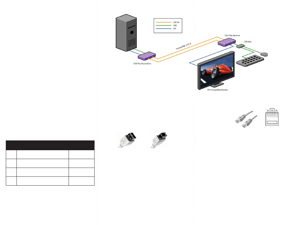
DVX Plus extends Universal Serial Bus (USB 1.1) and
Digital Visual Interface (DVI-D) signals via com-
mon twisted pair cable. Using a unique method of
transparent data transfer, the system allows a USB
peripheral and a DVI display to be located up to 275
feet from the CPU.
Features
Extends USB and DVI-D signals up to 275ft from
•
the computer.
Uses easy to install, inexpensive twisted pair
•
cable.
Data recovery for digital video.
•
Supports 1920x1200 digital video resolution.
•
Fully compliant with USB 1.1 specifications.
•
Supports 1.5 and 12 Mbps data rates.
•
Compatible with all operating systems.
•
External power adapter for transmitter and re-
•
ceiver unit.
Fully transparent (does not use any emulation).
•
Plug and play.
•
Preparing & Connecting System CAT5 Cable
Following is the wiring standard for terminating CAT 5 cable
using RJ-45 connector:
Pair 1
Pins 1 & 2
Pair 2
Pins 3 & 6
Pair 3
Pins 4 & 5
Pair 4
Pins 7 & 8
Connectors: RJ-45
Capacitance:
14 pf/ft (46.2 pf/m)
Conductor Gauge: 24 AWG
Impedance:
100 +/- 15 ohms
4
-
Pair
Operating Instructions
Once installation is completed verify that the power is
present at all devices in the system. If computer was on
during the set up it might be necessary to reboot the
computer. The peripheral devices should be ready for
use.
Connecting The Transmitter
Connect the transmitter to the host using an A-B
1.
USB cable.
Connect the transmitter to the host DVI-D using
2.
male to male DVI cable.
The A side of the USB connector would go to the
3.
computer host and the B side would be connected
to the transmitter.
Check that power LED is lit. The TX/RX LED should
4.
not be flashing at this time.
In the back of the unit connect the CAT5 cable that
5.
will connect to the receiver (DVXU-RX).
Connecting The Receiver
Connect the receiver to the peripheral device using
1.
A-B USB cable. In this case the A side of the connec-
tor will go to the receiver unit and the B side of the
connector will go the peripheral. Use a USB Hub if
needed.
Connect the receiver unit to the monitor.
2.
Join the DVX Plus units using shielded cable for
3.
DVI-D and standard CAT5/6 UTP cable for USB.
Once connected check that the Power LED on both
receiver and transmitter is on and the TX/RX LED is
flashing, indicating that communication exists be-
tween the two units. If receiver LED is not on, make
sure the power supply is connected.
DVX Plus Package Content
Qty
Items
Part No.
1
DVX Plus Transmitter unit
DVXU-TX
1
DVX Plus Receiver unit
DVXU-RX
2
5 volt dc power supply
PS-5D1A-US
Installation Diagram
A
B