Introduction, Features, Applications – Smart Avi DVX-PRO User Manual
Page 2: Installation, Optional ddc pass-through, Installation diagram
Introduction
The DVXPRO extends the distance between any
computer supporting single-link DVI-D and a
monitor or projector with a compatible DVI input.
Features
Top Image Quality at all Resolutions.
Video Resolutions up to 1920 x 1200 @ 60Hz
(1280 x 1024 @ 75Hz). on all distances up to
the maximum distance.
User selectable: DCC-Information used from
the remotely located monitor, from the locally
located Monitor or from an internal DDC
Table.
Basic device to remotely locate Touch Screen
and Sound.
Full duplex RS232 up to 150kbps.
Maximum Screen Resolution on all distances:
250 ft w/ STP Cat5e.
Compatible with all operating systems.
Compatible with all major Touch Screen and
Tablet.
Rack Mount options (19”): Mount up to 4 de-
vices in a 19”/1U rack mount kit.
Supports Stereo Sound.
Applications
Perfect Image Quality at all Resolutions.
Call Centers (co-locate user’s computers).
Installation
1.
Turn off computer and monitor.
2.
Connect DVI male to male cable between the
computer and the transmitter.
3.
Connect monitor or projector to the DVI port
on the receiver.
4. Connect RS232 port
5.
Connect audio cable
6.
Connect a shielded Cat 6 STP cable
between port 1 on the transmitter and port 1
on the receiver.
7.
Plug in the power transformers and connect
them to the transmitter and receiver.
8.
Turn on the monitor and computer.
Optional DDC Pass-Through
If you would like the computer to read EDID
information directly from your monitor instead of
the internal EEPROM in the DVXPRO, perform the
following steps.
1.
Turn off computer and monitor.
2.
Disconnect power adapters from transmitter
and receiver.
3.
Remove screws on the sides of the transmitter.
4.
Lift the top off of the chassis
5.
Locate headers labeled J12 and J13.
6.
Reconfigure the jumpers as shown.
7.
Replace chassis top and screws.
8.
Connect a second shielded Cat 6 STP cable
between port 2 on the transmitter and port 2 on
the receiver.
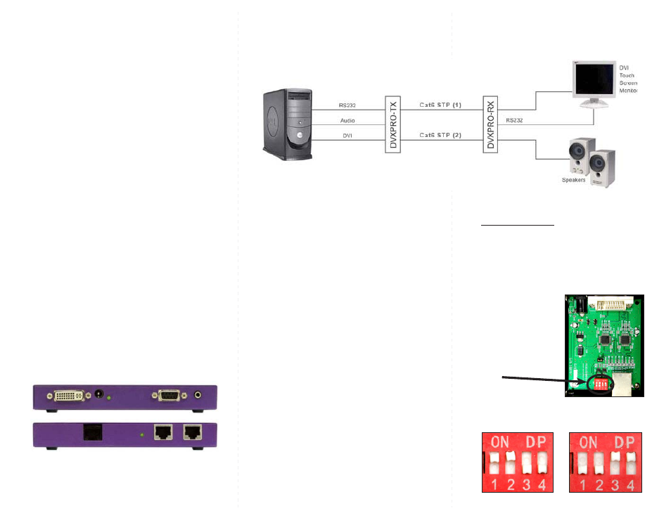
Installation Diagram
J13 J12
Setting the DDC
DDC provides plug-and-play capability to your
displays. When you plug a display into your computer,
the DDC table in the display tells the computer the
optimal resolution to use.
This device is capable of
supporting two primary types of displays: PC and Mac.
The default setting is PC.
For Mac, configure the
switches as shown below:
For PC, configure the
switches as shown below:
1&2 ON, 3&4 OFF
1&2 OFF, 3&4 ON
To change this setting,
first remove the top cover
from the TRANSMITTER
by removing the four side
screws. Next, locate the
DIP switches near the rear
of the device next to the
Data Port (RJ45 Ethernet
Port).