Introduction, Applications, Features – Smart Avi DVX-200 User Manual
Page 2: Setting the ddc, Dvi-d configuration, Technical specifications, Esolutions, Dvx-tx200 rear
Introduction
The DVX-200 is the perfect solution for extending DVI-D
signals to a remote location up to 225 feet away over
Cat6 23 AWG STP cabling. It is the ideal way to isolate a
workstation computer into one location and a console in
another. It is fully compatible with MAC, PC and LINUX
DVI-D single link standards.
Applications
•
Medical Applications
•
Industrial Work Areas
•
Home Theater Integration
•
Digital Signage Deployment
•
Information Kiosks/Displays
•
Film/Recording Studios
Features
•
Supports DVI-D single-link sources
•
Supports High Resolution 1920x1200 60Hz
WUXGA
•
Supports Mac, PC, and Linux DVI
•
Distance: 225 feet with Cat6 STP cabling
•
Uses universal DVI Single Link connectors
•
Zero pixel loss with TMDS signal correction
•
DDC from internal table for Mac/PC
•
Compatible with all operating systems
•
Compatible with all major KVM switches
•
Data recovery for digital video
•
Supports 1.5 and 12Mbps data rates
•
Plug-and-play
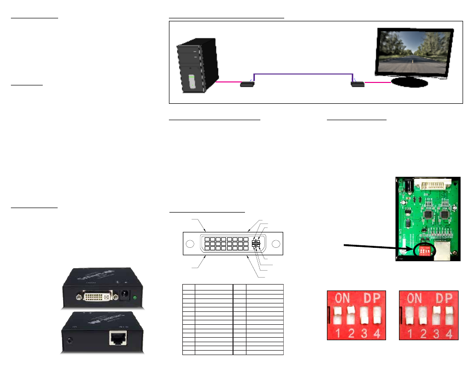
Product - Installation Diagram
Connecting the DVX-200
1. Power off all devices.
2. Connect a DVI-D source (computer) to the DVI-D
port on the rear of the DVX-TX200.
3. Connect the DVX-200-TX to the the DVX-RX200
with one STP (Sheilded Twisted Pair) cable.
4. Connect a DVI-D compatible display to the DVI-D
port on the rear of the DVX-RX200.
5. Connect the power to the DVX-RX200 and the
DVX-TX200.
6. Power on the display and then the computer.
Setting the DDC
DDC provides plug-and-play capability to your
displays. When you plug a display into your computer,
the DDC table in the display tells the computer the
optimal resolution to use. The DVX-200 is capable of
supporting two primary types of displays: PC and Mac.
The default setting is PC.
COMPUTER
DVI-D
DISPLAY
DVX-200
RECEIVER
DVX-200
TRANSMITTER
Up to 225 ft
over Cat6
DVI-D
DVI-D
Technical Specifications
Input/Output Signal
#
n
i
P
l
a
n
g
i
S
#
n
i
P
l
a
n
g
i
S
1
-
2
a
t
a
D
S
.
D
.
M
.
6
T
1
t
c
e
t
e
D
g
u
l
P
t
o
H
2
+
2
a
t
a
D
S
.
D
.
M
.
7
T
1
-
0
a
t
a
D
S
.
D
.
M
.
T
d
3
l
e
i
h
S
4
/
2
a
t
a
D
S
.
D
.
M
.
8
T
1
+
0
a
t
a
D
S
.
D
.
M
.
T
4
-
4
a
t
a
D
S
.
D
.
M
.
9
T
d
1
l
e
i
h
S
5
/
0
a
t
a
D
S
.
D
.
M
.
T
5
+
4
a
t
a
D
S
.
D
.
M
.
0
T
2
-
5
a
t
a
D
S
.
D
.
M
.
T
6
k
c
o
l
C
C
D
1
D
2
+
5
a
t
a
D
S
.
D
.
M
.
T
7
a
t
a
D
C
D
2
D
d
2
l
e
i
h
S
k
c
o
l
C
S
.
D
.
M
.
T
8
c
n
y
S
.t
r
e
V
g
o
l
a
n
3
A
2
+
k
c
o
l
C
S
.
D
.
M
.
T
9
-
1
a
t
a
D
S
.
D
.
M
.
4
T
2
-
k
c
o
l
C
S
.
D
.
M
.
T
0
1
+
1
a
t
a
D
S
.
D
.
M
.
T
1
d
1
l
e
i
h
S
3
/
1
a
t
a
D
S
.
D
.
M
.
1
T
C
d
e
R
g
o
l
a
n
A
2
1
-
3
a
t
a
D
S
.
D
.
M
.
2
T
C
n
e
e
r
G
g
o
l
a
n
A
3
1
+
3
a
t
a
D
S
.
D
.
M
.
3
T
C
e
u
l
B
g
o
l
a
n
A
4
1
r
e
w
o
P
V
5
4
+
C
c
n
y
S
z
r
o
H
g
o
l
a
n
A
5
1
D
N
5
G
C
d
n
u
o
r
G
g
o
l
a
n
A
PIN 17
PIN 1
PIN 24
PIN 8
C 4
C 1
C 2
C 5
C 3
esolutions
Suppo te
the inte nal
I configu atio
n
z
H
5
8
0
8
4
x
0
4
6
z
H
5
8
0
0
6
x
0
0
8
z
H
5
8
8
6
7
x
4
2
0
1
z
H
5
7
0
7
8
x
2
5
1
1
z
H
5
7
8
6
7
x
0
8
2
1
z
H
0
6
0
6
9
x
0
8
2
1
z
H
0
6
4
2
0
1
x
0
8
2
1
z
H
0
6
0
0
2
1
x
0
0
6
1
Resolution
Refresh Rate
5
C
1 6
DVI-D Configuration
DVX-TX200 Front
DVX-TX200 Rear
For Mac, configure the
switches as shown below:
For PC, configure the
switches as shown below:
1&2 ON, 3&4 OFF
1&2 OFF, 3&4 ON
To change this setting,
first remove the top cover
from the DVX-200
TRANSMITTER
by removing the four side
screws. Next, locate the
DIP switches near the rear
of the device next to the
Data Port (RJ-45 Ethernet
Port).