Introduction, Features, What’s in the box – Smart Avi XTAV User Manual
Page 2: Installation diagram introduction, Installation diagram
Introduction
The XT-av range of products allows the extension of
a wide range of video and audio formats via a single
Category 5 Unshielded Twisted Pair (UTP) cable.
Features
Uses easy to install, inexpensive CAT-5/5e/6/7/8.
Output reaches up to 1,000 feet (300 m).
Resolutions up to 1900x1200.
300 MHz Bandwidth.
Sends high-resolution UXGA, Stereo Audio and
Compatible with VGA, XGA, Sun, MAC and SGI
Sync Format / Polarity Preservation.
Compatible with Line Level Stereo Audio Signals.
High ground loop immunity.
Built-in lightning, power surge and transient
protection.
Designated trimmer in the remote unit to
compensate for cable length.
Compact Metal Case Enclosure.
What’s in the box?
XT-AV
Please check the contents of the package before
beginning installation.
Preparing & Connecting System CAT5 Cable
Following is the wiring standard for terminating CAT 5 cable
using RJ-45 connector:
Pair 1
Pins 1 & 2
Pair 2
Pins 3 & 6
Pair 3
Pins 4 & 5
Pair 4
Pins 7 & 8
Connectors: RJ-45
Capacitance:
14 pf/ft (46.2 pf/m)
Conductor Gauge: 24 AWG
Impedance:
100 +/- 15 ohms
4
-
Pair
Connecting The Transmitter
1.
Connect the output of the computer video card to the
video
input of the transmitter using the included male
to male video cable.
2.
Connect the output of the computer audio card to the
audio input of the transmitter using 3.5mm audio
male to male audio cable.
3.
Connect external speakers to the transmitter’s audio
out (Standard 3.5mm stereo miniplug).
4.
In the back of the unit connect the CAT5 cable that
will connect to the receiver (XTAV-RX).
Connecting The Receiver
Connect CAT5 cable (coming from the transmitter)
1.
to the back of the receiver.
Connect display monitors to the VGA out connec-
2.
tor on the front of the receiver.
Connect external speakers to the audio
3.
output connections on the front of the unit.
(Standard 3.5mm stereo Miniplug)
XT-AV Package Content
Qty
Items
Part No.
1
XT-AV Transmitter unit
XTAV-TX
1
XT-AV Receiver unit
XTAV-RX
2
5 volt dc power supply
PS-5D1A-US
1
HDD 15 male to male VGA cable
(6ft)
CC-VGAMM-06
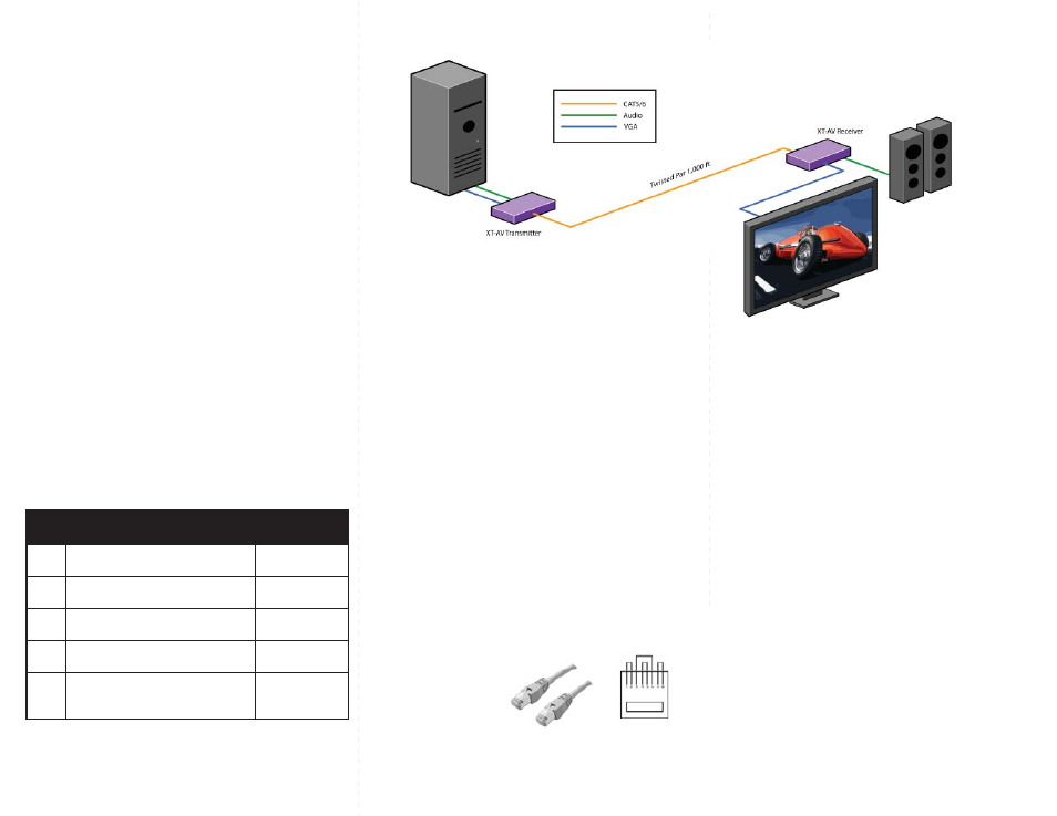
Installation Diagram
Introduction
The XT-av range of products allows the extension of
a wide range of video and audio formats via a single
Category 5 Unshielded Twisted Pair (UTP) cable.
Features
Uses easy to install, inexpensive CAT-5/5e/6/7/8.
Output reaches up to 1,000 feet (300 m).
Resolutions up to 1900x1200.
300 MHz Bandwidth.
Sends high-resolution UXGA, Stereo Audio and
Compatible with VGA, XGA, Sun, MAC and SGI
Sync Format / Polarity Preservation.
Compatible with Line Level Stereo Audio Signals.
High ground loop immunity.
Built-in lightning, power surge and transient
protection.
Designated trimmer in the remote unit to
compensate for cable length.
Compact Metal Case Enclosure.
What’s in the box?
XT-AV
Please check the contents of the package before
beginning installation.
Preparing & Connecting System CAT5 Cable
Following is the wiring standard for terminating CAT 5 cable
using RJ-45 connector:
Pair 1
Pins 1 & 2
Pair 2
Pins 3 & 6
Pair 3
Pins 4 & 5
Pair 4
Pins 7 & 8
Connectors: RJ-45
Capacitance:
14 pf/ft (46.2 pf/m)
Conductor Gauge: 24 AWG
Impedance:
100 +/- 15 ohms
4
-
Pair
Connecting The Transmitter
1.
Connect the output of the computer video card to the
video
input of the transmitter using the included male
to male video cable.
2.
Connect the output of the computer audio card to the
audio input of the transmitter using 3.5mm audio
male to male audio cable.
3.
Connect external speakers to the transmitter’s audio
out (Standard 3.5mm stereo miniplug).
4.
In the back of the unit connect the CAT5 cable that
will connect to the receiver (XTAV-RX).
Connecting The Receiver
Connect CAT5 cable (coming from the transmitter)
1.
to the back of the receiver.
Connect display monitors to the VGA out connec-
2.
tor on the front of the receiver.
Connect external speakers to the audio
3.
output connections on the front of the unit.
(Standard 3.5mm stereo Miniplug)
XT-AV Package Content
Qty
Items
Part No.
1
XT-AV Transmitter unit
XTAV-TX
1
XT-AV Receiver unit
XTAV-RX
2
5 volt dc power supply
PS-5D1A-US
1
HDD 15 male to male VGA cable
(6ft)
CC-VGAMM-06
Installation Diagram
Introduction
The HDX-PRO range of products allows the extension
of a wide range of video and audio formats, RS232,
and IR via a single Category 5 Unshielded Twisted
Pair (UTP) cable.
Features
Supports HDTV Screen
Y,Pb, Pr
Uses easy to install, inexpensive CAT-5/5e/6/7/8.
Output reaches up to 1,000 feet (300 m).
Resolutions up to 1900x1200.
300 MHz Bandwidth.
Sends high-resolution HDTV component, Stereo
Audio, RS232 and IR
Compatible with Line Level Stereo Audio Signals.
High ground loop immunity.
Built-in lightning, power surge and transient
protection.
Designated trimmer in the remote unit to
compensate for cable length.
Compact Metal Case Enclosure.
Supports RS232 and IR
What’s in the box?
HDX-PRO
Please check the contents of the package before
beginning installation.
Installation Diagram
Adjusting and Tuning the Signal
Adjusting and Tuning the Signal
Adjusting and Tuning the Signal
Adjusting and Tuning the Signal
Adjusting and Tuning the Signal
In order to fine tune the signal, adjust the individual
dials one at a time starting with GREEN, then BLUE,
and lastly RED. As you turn the dials you will notice
the colors slightly change as you increase or decrease
the strength. All dials should be around the same
distance.
Preparing & Connecting System CAT5 Cable
Preparing & Connecting System CAT5 Cable
Preparing & Connecting System CAT5 Cable
Preparing & Connecting System CAT5 Cable
Preparing & Connecting System CAT5 Cable
Following is the wiring standard for terminating CAT 5 cable
using RJ-45 connector:
Pair 1
Pins 1 & 2
Pair 2
Pins 3 & 6
Pair 3
Pins 4 & 5
Pair 4
Pins 7 & 8
Connectors:
Connectors:
Connectors:
Connectors:
Connectors:
RJ-45
Capacitance:
Capacitance:
Capacitance:
Capacitance:
Capacitance:
14 pf/ft (46.2 pf/m)
Conductor Gauge:
Conductor Gauge:
Conductor Gauge:
Conductor Gauge:
Conductor Gauge: 24 AWG
t
n
e
t
n
o
C
e
g
a
k
c
a
P
t
n
e
t
n
o
C
e
g
a
k
c
a
P
t
n
e
t
n
o
C
e
g
a
k
c
a
P
t
n
e
t
n
o
C
e
g
a
k
c
a
P
t
n
e
t
n
o
C
e
g
a
k
c
a
P
HDX-PROX
y
t
Q y
t
Q y
t
Q y
t
Q y
t
s
Q
m
e
tI
s
m
e
tI
s
m
e
tI
s
m
e
tI
s
m
e
t
.
I
o
N
t
r
a
P
.
o
N
t
r
a
P
.
o
N
t
r
a
P
.
o
N
t
r
a
P
.
o
N
t
r
a
P
y
2
l
p
p
u
s
r
e
w
o
p
c
d
tl
o
v
S
5
U
-
A
1
D
5
-
S
P
)
1
tf
6
(
e
l
b
a
c
A
G
V
e
l
a
m
o
t
e
l
a
m
5
1
D
D
6
H
0
-
M
M
A
G
V
-
C
C
l
a
n
o
it
p
O
l
a
n
o
it
p
O
l
a
n
o
it
p
O
l
a
n
o
it
p
O
l
a
n
o
it
p
O
e
1
l
b
a
c
g
u
l
p
i
n
i
m
o
e
r
e
t
s
m
m
5
.
3
o
i
d
u
6
A
0
M
M
D
A
-
C
C
1
r
e
v
i
e
c
e
R
E
Y
E
R
E
I
Y
E
-
M
S
1
r
e
tt
i
m
E
R
D
I
E
L
-
M
S
.
1
tf
6
9
B
D
f
/
m
l
a
ir
e
6
S
0
F
M
R
E
S
C
C
1 HDX-PRO Transmitter Unit HDX-PRO-TX
1 HDX-PRO Receiver Unit HDX-PRO-RX
Connecting The Transmitter
1. Connect the output of component video source to the
video input of the transmitter using RCA to RCA cable
2. Connect audio source to
the audio input of the transmitter using audio rca cable
5. In the back of the unit connect the CAT5 cable that
will connect to the receiver (XTPRO-RX).
*NOTE: You can not use RS232 and IR at the same time.
Connecting The Receiver
1. Connect CAT5 cable (coming from the transmitter) to
the back of the receiver.
2. Connect display monitors to the RCA
connectors on the front of the receiver.
3. Connect a sets of external speakers to the audio
output connections on the front of the unit.
DVD Player
IR
IR
HDX-PRO Transmitter Unit
HDX-PRO Reciever Unit
Remote Monitor
Cat 5
Audio
Video
Audio
Video
Speakers