Introduction, Features, What’s in the box – Smart Avi HDCVX User Manual
Page 2: Installation diagram, Installation instructions operating instructions, Connecting the ir, Connecting the transmitter, Connecting the receiver, Connect the transmitter to the receiver, Use the diagram for the ir connection
Introduction
The
HDC-VX
range
of
products
allow
the
extension
of
Video,
Stereo
Audio
and
Infra
R
ed
control
signals
using
single
CAT-5
UTP
(category
5,
unshielded
twisted
pair)
cable.
The
HDC-VX
is
the
first product
for
this
application.
Features
Uses
easy
to
install, inexpensive
CAT5.
Output
reaches up
to
1000
feet
(300
m).
Supports
PAL,
NTSC
and
SECAM.
Video
100
MHz
Bandwidth.
Video
cable
compensation.
Sends
Composite
Video,
Stereo
Audio,
IR
and
Power
signals
over
single
CAT5.
Compatible
with
Line
Level
Stereo
Audio
Signals.
High
ground
loop
immunity.
Built-in
lightning,
power
surge
and
transient
protection.
Remote
Units
come
with
Buffered
Outputs.
Compact
Enclosure.
Optional
power supply
for
remote unit.
Fully
compliant
with
standard
modulated
IR
a
n
d
the
latest
IRDA.
Fully
transparent path
for
all
protocols
and
data
transfers.
What’s
in
the
box?
HDC-VX
Please
check
the
contents
of
the
package before
beginning
installation.
Installation
Diagram
yt
Q
m
et
I
n
oi
t
pi
r
cs
e
D
1
1
1
1
D
E
L-
MS
E
Y
E-
MS
2
Installation
Instructions
Operating
Instructions
Once
installation
is
completed,
verify
that
the
power is
present
at
all
devices
in
the
system.
The
peripheral
devices
should
be
ready
for
use.
s
dr
a
d
n
at
S
g
ni
ri
W
5
T
A
C
#
niA
P8
6
5
AI
T/
AIB
E8
6
5
AI
T/
AI
E
e
1p
ir
ts
n
e
er
g
hti
w
eti
he
Wp
ir
ts
e
g
n
ar
o
hti
w
eti
h
W
n
2e
er
g
dil
os
r
o
e
pi
rt
s
eti
h
w
hti
w
n
e
er
G
e
g
n
ar
o
dil
os
r
o
e
pi
rt
s
eti
h
w
hti
w
e
g
n
ar
O
3
e
pi
rt
s
e
g
n
ar
o
hti
w
eti
h
W
e
pi
rt
s
n
e
er
g
hti
w
eti
h
W
e
4u
l
b
dil
os
r
o
e
pi
rt
s
eti
h
w
hti
w
e
ul
B
e
ul
b
dil
os
r
o
e
pi
rt
s
eti
h
w
hti
w
e
ul
B
e
5p
ir
ts
e
ul
b
hti
w
eti
he
Wp
ir
ts
e
ul
b
hti
w
eti
h
W
6
e
g
n
ar
o
dil
os
r
o
e
pi
rt
s
eti
h
w
hti
w
e
g
n
ar
O
dil
os
r
o
e
pi
rt
s
eti
h
w
hti
w
n
e
er
G
n
7w
or
b
dil
os
r
o
e
pi
rt
s
n
w
or
b
hti
w
eti
h
W
n
w
or
b
dil
os
r
o
pi
rt
s
n
w
or
b
hti
w
eti
h
W
n
8w
or
b
dil
os
r
o
e
pi
rt
s
eti
h
w
hti
w
n
w
or
B
n
w
or
b
dil
os
r
o
e
pi
rt
s
eti
h
w
hti
w
n
w
or
B
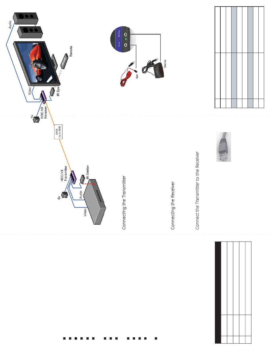
Connecting the IR
Use the Diagram for the IR connection.
Connecting the Transmitter
1. Connect the AV transmitter to your DVD, VCR,
satelliter receiver or other source of video signal.
2. Using RCA M-M cables , connect transmitter to audio
source.
3. Connect IR LED to the IR window on the source
device.
4. Connect power supply to the unit. Observe LED
lighting up indicating power present.
Connecting the Receiver
Connect receiver to the display, typically a TV
monitor using Video cable (not included) and audio
cable RCA Male to Male.
Connect the Transmitter to the Receiver
Connect the transmitter to the receiver using
Category 5 UTP cable (Purchased separately). The
CAT 5 UTP cable, if purchased in
bulk, will be wired using 568A or
568B wiring standard. Once
connected, check that the power
LEDs on both the receiver and the
transmitter are on, IR status LED is on and RX LED is
flashing when Remote control is used indicating that
communication is in progress.
HDC-VX-TX
HDC-VX-RX
PS5VD1A
Video/Audio/IR Transmitter
Video/Audio/IR Receiver
IR Emitter
IR Eye “Optional”
Power supply 5VDC1A