Sensoray 335 User Manual
Page 11
11
LEDs
The LED D1 and D2 are used for indicating the status of PCMCIA PC-cards:
D1 (Red) -- for Slot#-Top
D2 (Red) -- for Slot#-Bottom
For both D2 and D2:
On -- card inserted and active
Off -- no card inserted or inactive
The LED D5 is used for indicating the status of Power-Ok:
On -- Power is good
Off -- Power is not good or not on the board
Configuration DIP Switches
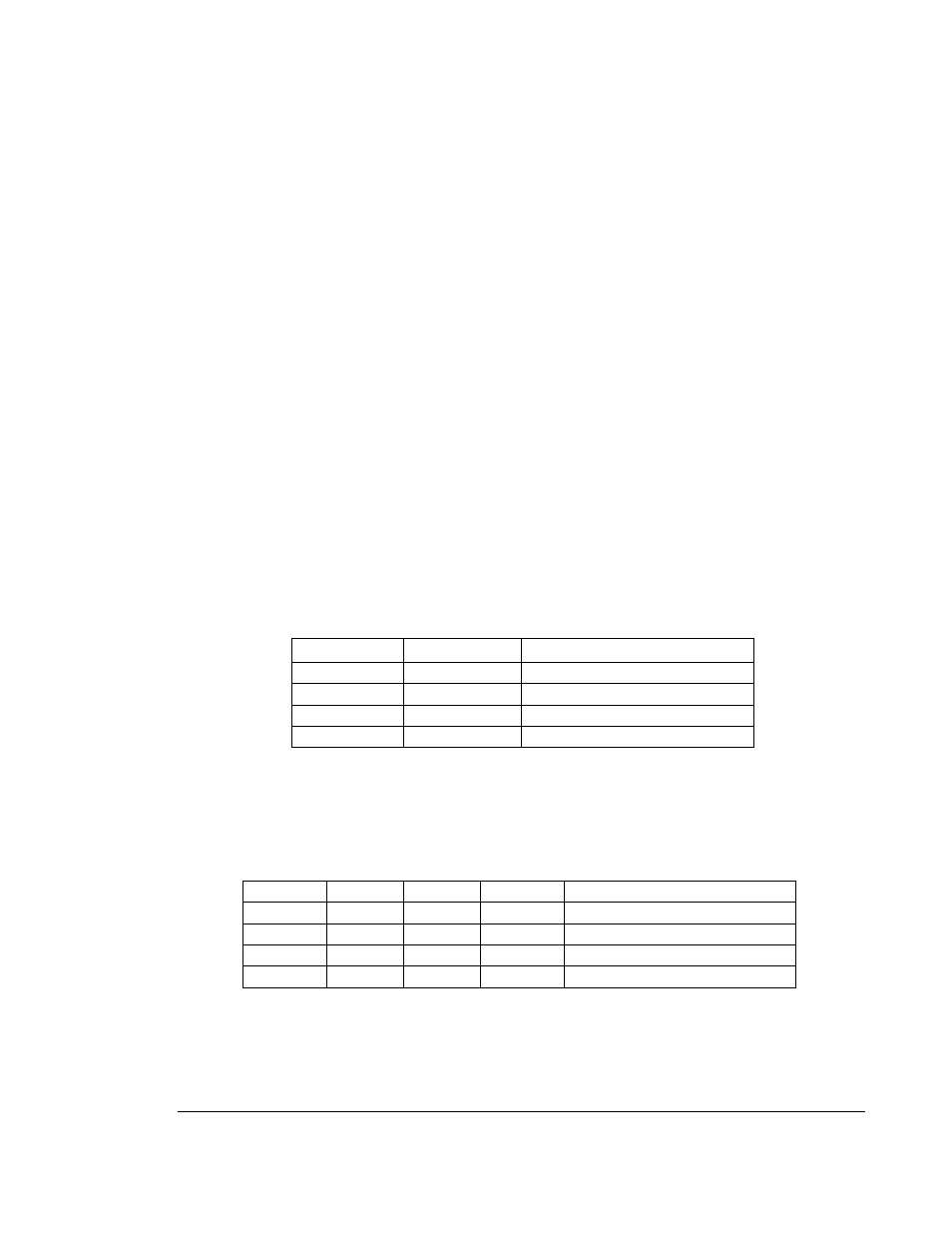
Slot# selection, SW1
The DIP switch SW1 is used for selecting the PC/104+ module slot number. Refer to the table blow
for slot number selection.
SW1-1
SW1-2
Module Slot #
on
on
Slot#0
off
on
Slot#1
on
off
Slot#2
off
off
Slot#3
Interrupt routing selection, SW2
The DIP switch SW2 is used for selecting an interrupt routing for the PC card controller TI PCI-
1520 to submit the interrupt. Refer to the table blow for the routing selection.
SW2-1
SW2-2
SW2-3
SW2-3
Interrupt Routing
on
off
off
off
INTA#
off
on
off
off
INTB#
off
off
on
off
INTC#
off
off
off
on
INTD#
- 2226 (15 pages)
- 2253 (19 pages)
- 616 (8 pages)
- 516 AVStream DirectShow (10 pages)
- 2246 (42 pages)
- 2246 (50 pages)
- 2255 (33 pages)
- 614 (17 pages)
- 611 (7 pages)
- 314 (14 pages)
- 614 Caption Overlay (18 pages)
- 311 (9 pages)
- 314 Quick Start (14 pages)
- 1012 (12 pages)
- 810 Quick Start (7 pages)
- 953-ET (17 pages)
- 911 (17 pages)
- 812 (16 pages)
- 810 (15 pages)
- 615 (8 pages)
- 615 (15 pages)
- 711 (36 pages)
- 609 (17 pages)
- 817 (11 pages)
- 817 (18 pages)
- 2411 (11 pages)
- 2250 (6 pages)
- 2263 (12 pages)
- 2263 (25 pages)
- 2480 (10 pages)
- 2453 (27 pages)
- 819 (11 pages)
- 516 (8 pages)
- 3011S (29 pages)
- 2444 (19 pages)
- 7429 (48 pages)
- 718 (22 pages)
- 518 (57 pages)
- 526 (29 pages)
- 526 (7 pages)
- 826 (76 pages)
- 2426 (17 pages)
- 721 (13 pages)
- 2410 (9 pages)
- 2600 (80 pages)