Iv. installation, Iii. specifications – San Jose Technology MK-18 User Manual
Page 3
IV.
INSTALLATION
1.
Secure your MK-18 antenna to the top of your vehicle and carry its
cable into the vehicle.
2.
Link the cable connector to your GPS receiver.
3.
Start with your navigation.
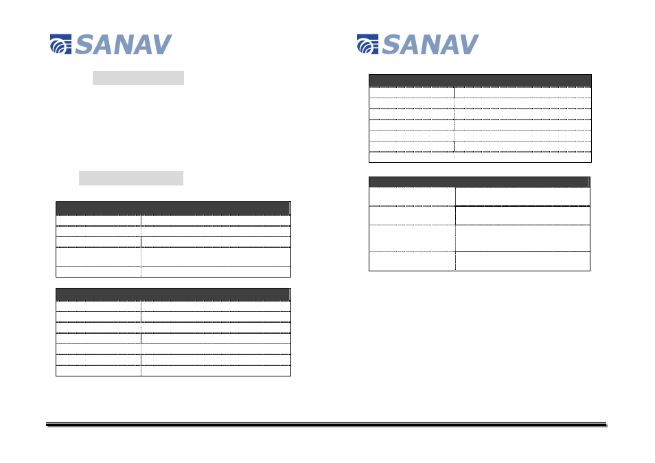
III. SPECIFICATIONS
PHYSICAL CONSTRUCTION
Construction:
Polycarbonate radome on metal base
Dimension:
33.95mm (L) x 25.20mm (W) x 10.60mm (H)
Weight:
30 grams (excluding cable & connector)
Color of Radome:
Standard in dark gray, other colors available upon
request
Standard Mounting:
Magnet or screw mount
ANTENNA ELEMENT
Center Frequency:
1575.42 MHz +/- 1.023 MHz
Polarization:
R.H.C.P. (Right Hand Circular Polarization)
Absolute Gain at Zenith:
+5 dBi typically
Gain at 10
o
Elevation:
-1 dBi typically
Axial Ratio:
3 dB Max.
Output VSWR:
1.5 Max.
Output Impedance:
50 ohm
LOW NOISE AMPLIFIER
Center Frequency:
1575.42 MHz +/- 1.023 MHz
Band Width:
2 MHz min.
Noise Figure:
1.5 Max.
Out Band Attenuation:
20dB min. @F0 +/- 50MHz
Supply Voltage:
1.8~3.3 V DC
VSWR:
1.5 Max.
Output Impedance:
50 ohm
CABLE & CONNECTOR
RF Cable:
3 meter RG174/U (standard), other length
available
Pulling Strength:
6 Kg/5 sec. with molded plastics on
connector end for strain relief
Connector Available:
BNC, TNC, FME (to be adapted), GT5,
MCX (OSX), SMA, SMB or SMC in straight
or right angle type
Optional Adapters:
FME~MCX, FME~BNC, FME~SMA,
FME~SMB, FME~TNC