Typical compressed air distribution system – Delta 66-750 User Manual
Page 12
12-ENG
D26269
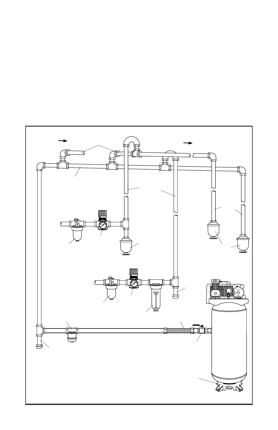
DRAIN
TRAP
DRAIN
TRAPS
DRAIN
LEGS
MOISTURE
SEPARATOR
AND TRAP
DIRT
LEG
DIRT
LEG
LUBRICATOR
REGULATOR
FILTER
AIR DISCHARGE
VALVE
LUBRICATOR
MAIN DISTRIBUTION AIR LINES
Slope pipe down in direction of air flow.
Water condensate flows along
bottom of pipe to drain legs,
preventing it from entering feeder
lines.
REGULATOR
FLEXIBLE
COUPLING
DRAIN COCK
VALVE
TYPICAL COMPRESSED
AIR DISTRIBUTION SYSTEM
AIR FLOW
AIR FLOW
FEEDER LINES SLOPE
WITH AIR FLOW
AIR USAGE
LINES
AIR
COMPRESSOR
● Use pipe that is the same size as the air tank outlet. Piping that is too
small will restrict the flow of air.
● If piping is over 100 feet long, use the next larger size.
● Bury underground lines below the frost line and avoid pockets where
condensation can gather and freeze. Apply pressure before underground
lines are covered to make sure all pipe joints are free of leaks.
● A flexible coupling is recommended to be installed between the air
discharge outlet and main air distribution line to allow for vibration.
● A separate regulator is recommended to control the air pressure. Air
pressure from the tank is usually to high for individual air driven tools.