RF Neulink NL900PRO User Manual
Page 8
C H A P T E R 3 - S E R I A L I N T E R F A C E
6
R S 4 8 5 ( 2 - W I R E )
The RS-485 interface uses a Differential Data Transmission that can help nullify the effects of ground shifts
and induced noise signals that can appear as common mode voltages on a network.
The NL900PRO implements a RS-485 (2-wire Half Duplex) multi-drop interface. Typically, a RS-485 bus will
consist of a master and several slaves. The nodes will have unique addresses and can send addressed
packets to specific nodes. Because the bus is half duplex, no two nodes should try to talk at the same time.
The NL900PRO does not have a RS-485 address, therefore, it will transmit all RS-485 traffic over the RF.
Conversely, as soon as a NL900PRO receives a packet over the RF, it will transmit the packet over the RS-
485 bus.
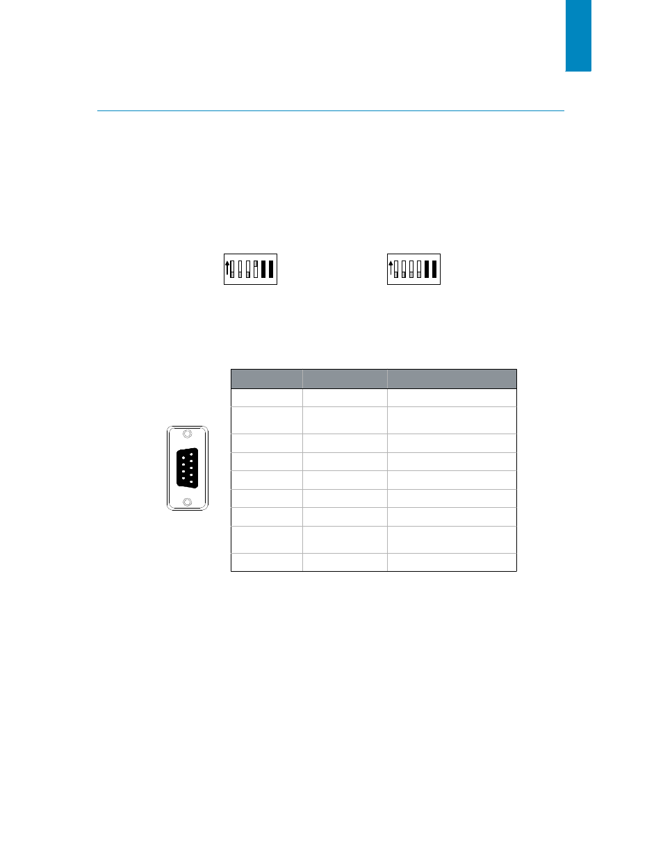
F i g u r e 4 : R S 4 8 5 H a l f D u p l e x w i t h Termination D I P S w i t ch S et tings
ON
ON
1 2 3
4 5 6
1 2 3
4 5 6
With Termination
1
Without Termination
1. Termination is a 120 ohm resistor between TR- and TR+.
T A B L E 4 : N L 9 0 0 P R O R S 4 8 5 P I N O U T
D B 9 P I N
S I G N A L N A M E
D E S C R I P T I O N
1
-
No Connect
9
5
6
1
Female DB9
2
TR-
Serial Data transmitted to &
received from radio
3
-
No Connect
4
-
No Connect
5
GND
Ground
6
-
No Connect
7
-
No Connect
8
TR+
Serial Data transmitted to &
received from radio
9
Power
Optional Power Input
1
1. An internal jumper must be configured in order to use power over Pin 9.