Technical data wiring diagram – REMKO ETF 100 User Manual
Page 14
14
Technical Data
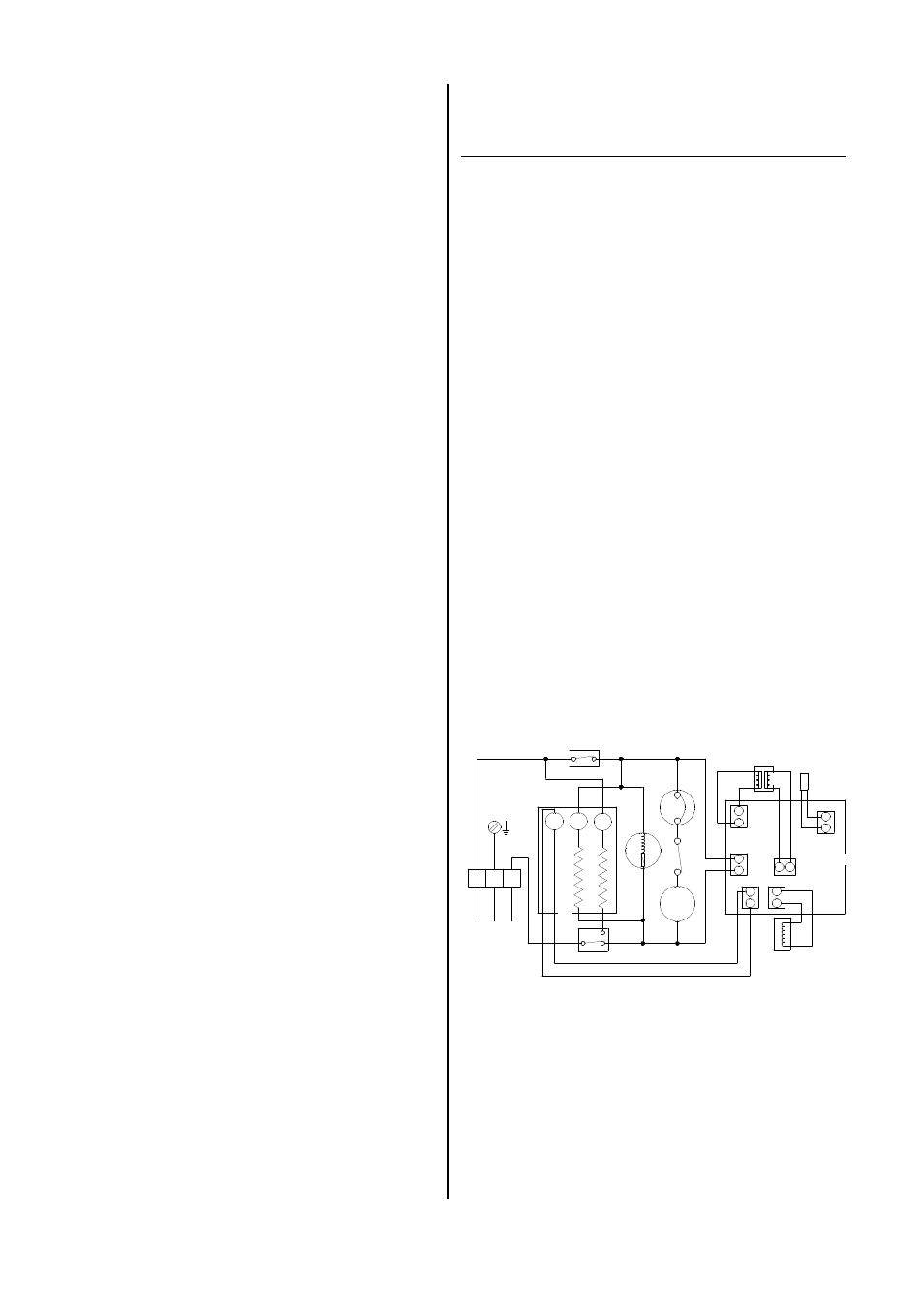
Wiring Diagram
PN = Power board
PS = Control board
R = Protective resistor
SK = Starting unit
SR = Start relay
TS = Temperature sensor
TR = Transformer
Model ETF 100 ETF 150
Working temperature range °C 6 - 32 6 - 32
Working humidity range % rel. 40-100 40-100
Max. dehumidification l/day 14 15
at 30 °C / 80% rel. hum. l/day 12 13
Air performance m³/h 115 105
Refrigerant R134a R 134a
Refrigerant volume g 200 200
Electrical connection V 230/1~ 230/1~
Frequency Hz 50 50
Max. nominal current A 2,5 2,5
Max. power consumption W 395 395
Circuit breaker (building) A 10 10
SPL L
pA
1m
1)
dB (A) 45 45
Dimensions depth mm 310 310
width mm 300 300
height mm 570 570
Weight kg 17.0 17,5
1) noise measurement as per DIN 45635 - 01 - KL 3
H = Hygrostat
KL = Terminal strip
LA = LED - defrost
LB = LED - operation
LT = LED - tank full
M = Fan motor
MK = Compressor
MS = Microswitch
MV = Solenoid
PA = Display board
Unit does not start:
◊
Check AC power.
230V/1~ 50 Hz.
◊
Check permanently installed circuit breaker.
10 A.
◊
Check power plug.
◊
Check condensation tank for fill level and proper
seating.
Red warning lamp lit.
◊
Check micro switch function.
◊
Check hygrostat settings.
Setting must be lower than the humidity in the room.
Unit running, no condensation formation:
◊
Check room temperature.
The working range of the unit is between 6°C and
32°C.
◊
Check relative humidity.
Min. 40%.
◊
Check hygrostat setting and choose a lower setting if
required
◊
Check air intake filter/charcoal filter for contamination.
Clean or replace as required
◊
Check exchanger blades for soiling.
Lei it clean as required.
◊
Vaporizer is heavily iced up.
Check automatic defrosting and/or room temperature.
◊
Vaporizer temperature not under room temperature.
Check automatic defrosting and/or compressor
Unit is too loud (vibration) or leaks condensation:
◊
Unit standing on uneven surface (not upright).
◊
Plug not correctly installed.
1. in the drain of condensation trap.
2. in the hose connector on rear panel.
Should the unit still not be working despite these
checks, please contact an authorised service centre.
TS
TR
MV
LA
SK
MK
M
LB
LT
MS
H
KL
230V/1~ 50 Hz
N PE L1
SR
R
R
PN
PS
PA
Always remove the power plug from the plug
socket when working on the unit!
In Case of Troubles
The functions of this dehumidifier were tested several
times during the course of its production.
Should a fault occur nevertheless, please check the fol-
lowing points in the order listed below.
Repairs of the cooling and electrical systems
may only be performed by an authorised serv-
ice centre!