Wiring diagram, Th ms1, Pcb2 pcb1 – REMKO RKL 460 User Manual
Page 13: Wm ms2, Cn6 cn7
13
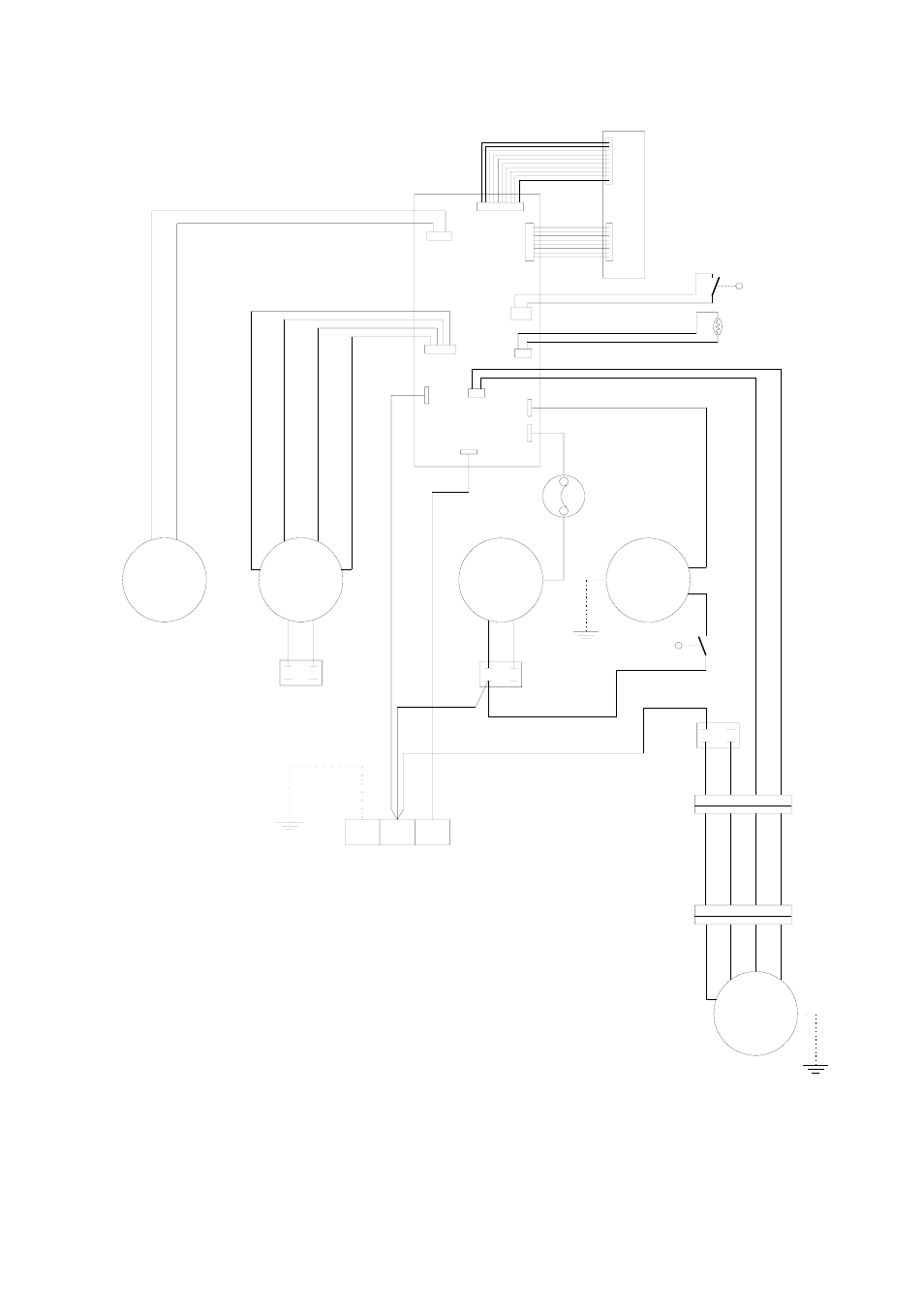
Wiring Diagram
CM
PE
N
L
CX1
SM
FM1
CM
FM2
CX3
CX2
OLP
AC2
WM
AC1
CN1
CN5
CN4
TH
MS1
P001B
P002B
CN2
PCB2
PCB1
R
BK
BU
BU
BR
W
BU
BU
BU
R
R
R
GR
BK
BR BR
Legende
PCB2 = Steuerplatine
SM
= Swing-Motor
FM1
= Lüftermotor Innengerät
FM2
= Lüftermotor Außenteil
WM
= Kondensatpumpe
CM
= Verdichter
OLP
= Verdichterschutz
CX1
= Kondensator (FM1)
CX2
= Kondensator (FM2)
CX3
= Kondensator (CM)
TH
= Temperatursensor
MS1
= Mikroschalter (Tank voll)
MS2
= Mikroschalter (Pumpe)
PCB1 = Bedientableau
CN3
WM
MS2
BU
BU
BR
BK
Y
BU BR
BK
Y
CN6
CN7
C
S
R
OR
W
BU
Y
BU BR
BK
Y
Farbkennzeichnung
W
= Weiß
R
= Rot
BU
= Blau
BR
= Braun
BK
= Schwarz
GR
= Grau
OR
= Orange
Y
= Gelb
We reserve the right to make modifications in dimensions and construction in the interests of technical progress.
PCB1 = Control panel
PCB2 = Control board
SM =
Swing motor
FM1 = Fan motor (indoor unit)
FM2 = Fan motor (outdoor unit)
WM =
Water pump
CM =
Compressor motor
OLP = Overload protection (compressor)
CX1 = Capacitor fan motor (indoor unit)
CX2 = Capacitor fan motor (outdoor unit)
CX3 = Capacitor (compressor motor)
TH =
Thermostat sensor
MS1 = Micro switch (water tank full)
MS2 = Micro switch (water pump on/off)
Y = yellow
W = white
R = red
BU = blue
BR = brown
BK = black
GR = grey
OR = orange