Link - (unbalanced jack), Pad - (switch), Filter - (switch) – Proel DB1P User Manual
Page 2: Bal output - (male xlr), Gnd lift - (switch), Rack mounting
SPECIFICATION
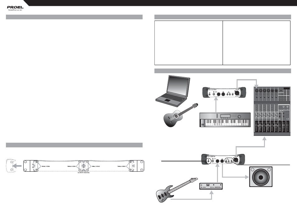
EXAMPLES
CONTROLS AND AUDIO CONNECTION
1. INPUT - (unbalanced JACK or RCA)
Connect the source instrument to this 1/4” jack or rca pin socket to receive the signal. The input impedance depends
by PAD setting: 120 Kohm with no pad, 47 Kohm with pad insertion.
2. LINK - (unbalanced JACK)
Connect this 1/4” jack to the input of the backline instrument or monitor amplifi er.
NOTE: If you are using a tube amplifi er power output (4, 8 or 16 ohm), you must connect always a speaker
of matched impedance in parallel, also using the LINK jack on DB1-P; for these connections you have to use
always jack-jack power cables avoiding jack-jack signal cables.
3. PAD - (switch)
The pad switches reduce the input signal to the circuit to ensure a clean and distortion-free signal.
Four steps are possible: -20 dB (no pad), -40 dB (left only), -60 dB (right only), -80 dB (both). Always use as little
as attenuation as possible to get the best possible signal with reference to the noise fl oor. The highest attenuations
make possible to connect the DB1-P to any amplifi er output without saturate the mic input of your mixer desk.
4. FILTER - (switch)
The fi lter switch insert a gentle fi lter after 4KHz to simulate the behaviour of a guitar 12” speaker amplifi er. This
switch has an eff ect only if one or more PAD switches are pressed.
5. BAL OUTPUT - (male XLR)
This male XLR output connector is the balanced microphone level output of the DI and it is wired with pin-1 ground,
pin-2 hot and pin-3 cold.
6. GND LIFT - (switch)
Use the GND LIFT switch to either connect the ground pin of input and output or keep them fully separated.
Depending on the grounding of the connected devices linking or disconnecting will reduce hum and buzz noises
and prevent ground loops.
NOTE: Always make sure the GND LIFT is pressed (no ground link) when connecting to speaker terminals,
this prevents accidental short-circuiting of the amplifi er output. Also make sure the TIP of the input jack is
connected to the red wire and that the metal chassis of the DB1-P has no contact with other equipment.
RACK MOUNTING
Simply removing the two molded sides and attaching two units with the supplied brackets you can mount two by
two DI boxes into a standard 19” rack.
System Type
1 channel passive DI
System Performance
Input Section
Insertion loss
20 dB
Input Impedance
120K Ohm (pad at 0 dB)
CMR
> 100 dB
47k Ohm (pad at -20/-60 dB)
Phase distortion
0° at 20 Hz, 0° at 20k Hz
44k Ohm (pad at -40 dB)
Distortion THD 50÷20k Hz 0dBu
< 0.007 %
Max Input Level
+15 dBu (pad at 0 dB)
Noise
< -105 dBu unweighted
+35 dBu (pad at -20 dB)
Frequency Response
10 Hz to 100 kHz, +0dB/-1 dB
+55 dBu (pad at -40 dB)
+75 dBu (pad at -60 dB)
Controls
Pad -20, Pad -40, Gnd Lift, Filter (12" emulator)
Connectors
Two Parallel 1/4" jack connectors and one
Indicators
none
parallel RCA connector (unbalanced)
Jack: Tip Hot / Sleeve Ground
General
XLR female: Pin 2 Hot / Pin1 & 3 Ground
Phantom Power
unnecessary
Output Section
External AC/DC adaptor
unnecessary
Output
Transformer Balanced (isolated with shielding)
Standalone/Standby
unnecessary
Max. Output Level
into 1K Ohms or greater
Current consumption
unnecessary
-5 dBu (for 0.1% THD at 50 Hz)
+5 dBu (for 0.1% THD at 1k Hz)
Dimensions (W x H x D)
215 x 50 x 125 mm
Connector
XLR male: Pin 2 Hot / Pin 3 Cold / Pin1 Ground
Weight (excluding batteries)
1 Kg
or
or
mono CH
(unbal - hi-z)
speaker link
shielded signal cable (jack unbal)
instrument
instrument
amplifier
instrument
speaker
long cables (XLR balanced)
amplifier power out
power cable (jack-jack)
power cable (jack-jack)
GND LIFT must be always pressed
set PAD switches to -20 or -40 or -60
to have a signal without distortion
long cables (XLR balanced)