9v battery holder, 9vdc input/link, Rack mounting – Proel DB1A User Manual
Page 2: Link - (unbalanced jack), Pad - (switches), Sign - (green led), Clip - (red led), Ø rev - (switch), Bal output - (male xlr), Power - (switch)
equipment.
11. 9V BATTERY HOLDER
For best reliability and long life, we recommend you use only high quality alkaline battery.
12. 9VDC INPUT/LINK
Alternatively to phantom or battery power you can use also an external 9 V DC adaptor. A LINK socket is provided
if you have to power more than one unit installed into a rack.
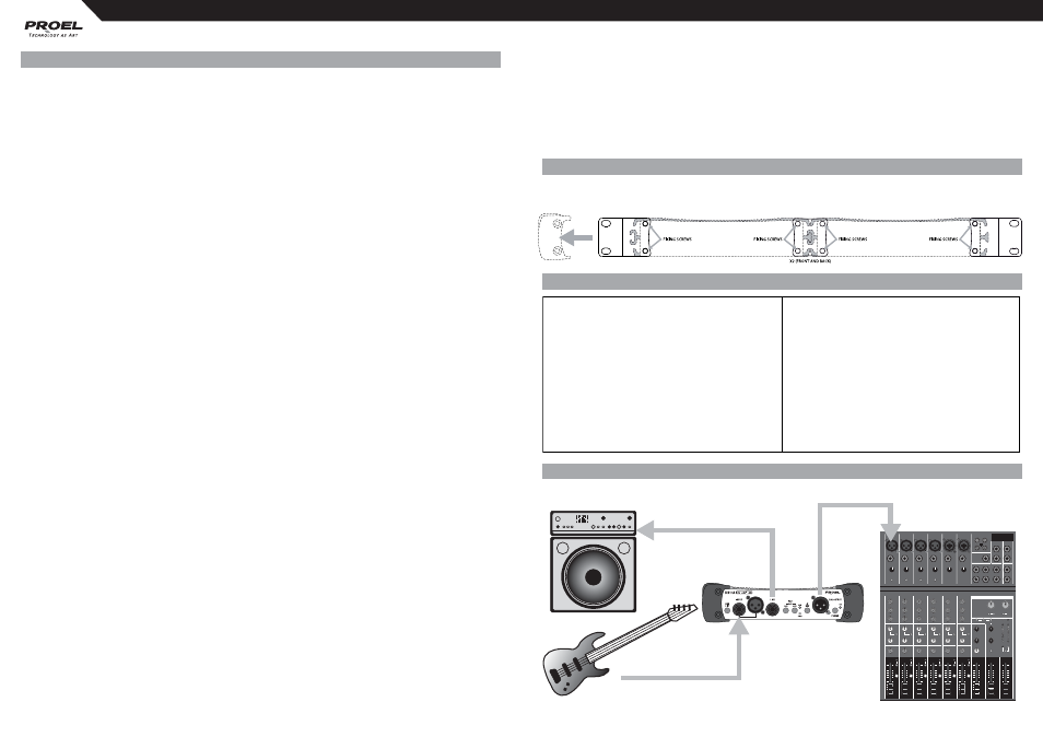
RACK MOUNTING
Simply removing the two molded sides and attaching two units with the supplied brackets you can mount two by
two DI boxes into a standard 19” rack.
SPECIFICATION
EXAMPLE (electric bass guitar)
CONTROLS AND AUDIO CONNECTION
1. INPUT - (unbalanced JACK or female XLR)
Connect the source instrument to this 1/4” jack to receive the signal. The input impedance depends on PAD setting:
1 Mohm with no pad, 47 Kohm with pad insertion.
2. LINK - (unbalanced JACK)
Connect this 1/4” jack to the input of the backline instrument or monitor amplifi er. By factory it is directly connected
at the input; but by changing two internal jumpers (J1 and J2) it is possible to set it as buff ered output.
3. PAD - (switches)
The pad switches reduce the input signal to the circuit to ensure a clean and distortion-free signal.
Four steps are possible: 0 dB (no PAD), -10 dB (left only), -20 dB (right only), -30 dB (both). Always use as little as
attenuation as possible to get the best possible signal with reference to the noise fl oor.
4. SIGN - (green led)
The SIGN (green) led shows when an input signal is present.
5. CLIP - (red led)
The CLIP (red) led lights up when the signal is at 6 dB before real clip, showing when an excessive input signal is
present. If this led lights up very often, press one or more pad switches to reduces the input signal.
6. Ø REV - (switch)
The Ø REV switch reverse the phase of the signal at the balanced output. It can be also used when combining two
sources (mic & DI) on the same instrument to avoid phase cancellation.
7. BAL OUTPUT - (male XLR)
This male XLR output connector is the balanced microphone level output of the DI and it is wired with pin-1
ground, pin-2 hot and pin-3 cold. To power the DI box it must be connected to the phantom powered MIC input
of the mixing console. Connecting the DI box to a mixer LINE input the DI box must be powered with battery or
AC/DC adaptor.
8. POWER - (switch)
The power switch is used for both battery and external adaptor power. To avoid battery drain when the unit is not in
use, ensure that this switch is set to the OFF position when storing the DB1-A. The power switch has not infl uence
when the DB1-A is powered by the phantom power of a MIC channel.
NOTE: To prevent damaging of your speaker and avoid switching noise, fi rst connect the DI box and then
hook up the respective channel or mute the mix channel before activating or connecting the DB1-A.
9. ON - (green led)
The ON (green) led shows when the DB1-A is powered. If the led doesn’t light, be sure that the phantom power of
the channel where the DB1-A is connected is activated.
10. GND LIFT - (switch)
Use the GND LIFT switch to either connect the ground pin of input and output or keep them completely separated.
Depending on the grounding of the connected devices linking or disconnecting will reduce hum and buzz noises
and prevent ground loops.
NOTE: Always make that sure the GND LIFT is pressed (no ground link) when connecting to speaker
terminals, this prevents accidental short-circuiting of the amplifi er output. Also make sure the TIP of the
input jack is connected to the red wire and that the metal chassis of the DB1-A has no contact with other
long cable (XLR balanced)
jack-jack link (unbalanced)
hi-z pickup (jack unbal)
System Type
1 channel active DI
System Performance
Input Section
Insertion loss
< 1 dB
Input Impedance
1M Ohm (pad at 0 dB)
CMR
> 60 dB
47k Ohm (pad at -10/-20 dB)
Phase distortion
+14° at 20 Hz, -6° at 20k Hz
44k Ohm (pad at -30 dB)
Distortion THD 50÷20k Hz 0dBu
< 0.007 %
Max Input Level
+5 dBu (pad at 0 dB)
Noise
< -105 dBu unweighted
+15 dBu (pad at -10 dB)
Frequency Response
10 Hz to 100 kHz, +0dB/-1 dB
+25 dBu (pad at -20 dB)
+35 dBu (pad at -30 dB)
Controls
On/off, Pad -10, Pad -20, Gnd Lift, Ø inv.
Connectors
Two Parallel 1/4" jack connectors and one
Indicators
On, signal, clip
parallel XLR connector (unbalanced)
Jack: Tip Hot / Sleeve Ground
General
XLR female: Pin 2 Hot / Pin1 & 3 Ground
Phantom Power
+24 volts DC to +48 volts DC
Output Section
External AC/DC adaptor
+9 volts DC
Output
Transformer Balanced (fully isolated)
Standalone/Standby
9 volt PP3 type, battery preferably alkaline.
Max. Output Level
into 600 Ohms or greater
Current consumption
less than 8 mA
+3 dBu (for 0.1% THD at 50 Hz)
+5 dBu (for 0.1% THD at 1k Hz)
Dimensions (W x H x D)
215 x 50 x 125 mm
Connector
XLR male: Pin 2 Hot / Pin 3 Cold / Pin1 Ground
Weight (excluding batteries)
1 Kg