Lm/tm-3315 series, A. tilting lcd panel, B. cable cover routing – Posiflex LM-3315 User Manual
Page 7
Part 7
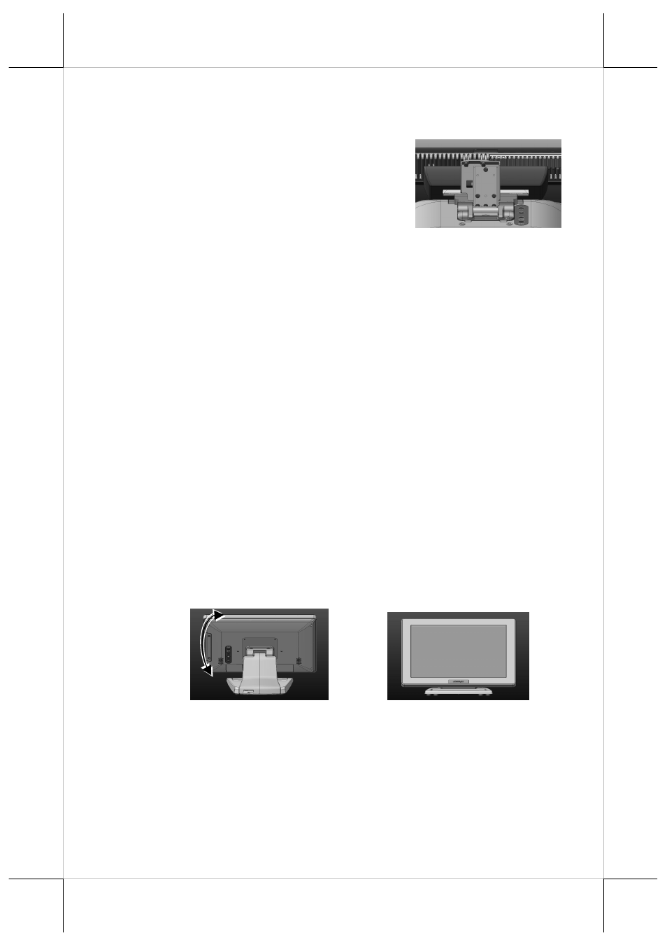
Please do the following steps to install LM/TM-3215/KS:
Step A): Hold the LM-3215/KS 2
nd
LCD
monitor with bracket and aim to join
bracket which is just fixed on the KS
series POS main unit and fasten these
3 pcs short screws which are circled
in the right picture.
Step B): Connect the VGA Cable to the LM VGA port and route the VGA
cable through the cable exit hole of KS base stand to the system
VGA port on the I/O plate.
LM/TM-3315 Series
A. TILTING LCD PANEL
Please do the following steps to tilt LCD panel:
Step A): Hold and push downward the main unit indicated
Step B): Tilt the neck at its right position for most suitable angle for
best view effect and convenience in cable
connection/disconnection.
B. CABLE COVER ROUTING
Please do the following steps to remove the cable cover from slim base.
Step A): Release the plastic neck cover.
Step B): Route the cable to the circled holes.
B
A