Located at a t an ol lt v 25, Output connec, An ctions - const ta – Paso Sound DMA2015B User Manual
Page 13: Olt const v vo olt or a 70 ution syst strib, Ge dist a t ta ol lt v nt, Oltage method v vo tant tems - in application, Ution syste trib, D is most widely used ing a large ns requir, D. ers umber of speak n, S that are
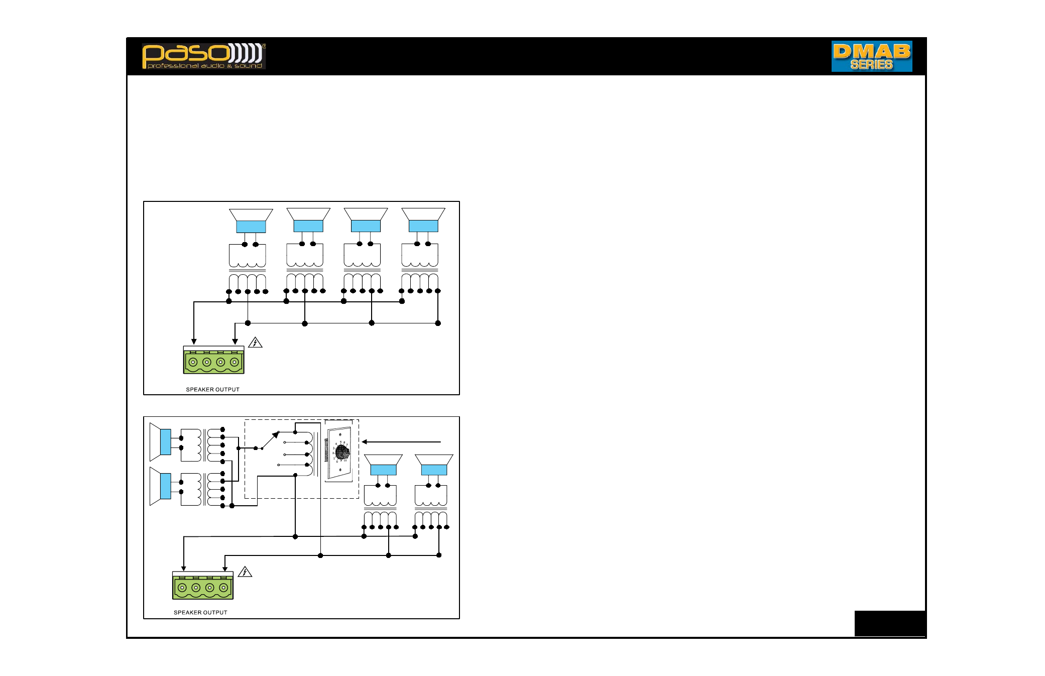
OUTPUT CONNECTIONS - CONSTANT VOLTAGE DISTRIBUTION SYSTEM
RM 013
DMA spkout05
0.6
5
0
2.5
1.25
0.6
5
0
2.5
1.25
0.6
5
0
2.5
1.25
0.6
5
0
2.5
1.25
spk 1
spk 2
spk 3
spk 4
70 Volt
Transformer
70 Volt
Transformer
70 Volt
Transformer
70 Volt
Transformer
Total Speaker Load Calculation
T
L
= SPK1+SPK2+SPK3+SPK4
T
L
=1.25+1.25+2.5+5 = 10 Watt
COM
8
25V 70V
DMA spkout06
0.6
5
0
2.5
1.25
0.6
5
0
2.5
1.25
spk 3
spk 4
70 Volt
Transformer
70 Volt
Transformer
Total Speaker Load Calculation
T
L
= SPK1+SPK2+SPK3+SPK4
T
L
= 2.5+2.5+2.5+2.5 = 10 Watt MAX.
0.6
5
0
2.5
1.25
spk 1
70 V
olt
T
ransf
ormer
0.6
5
0
2.5
1.25
spk 2
70
V
olt
T
ransf
ormer
RED
BLUE
BLA
CK
PASO VC20 ATTENUATOR
COM
8
25V 70V
Fig. 03B - Using a Speaker Attenuator Diagram
Fig. 03A - 70 Volt Constant Voltage System Diagram
25 VOLT AND 70 VOLT CONSTANT VOLTAGE DISTRIBUTION SYSTEMS - In applications requiring a large number of speakers that are
located at a far distance from the amplifier a 25 Volt or a 70 Volt Constant Voltage method is most widely used.
MAIN ADVANTAGES IN USING THE HIGH IMPEDANCE METHOD
1) All speakers are connected in parallel usually on to a single speaker line.
2) The Amplifier Output Voltage is constant over a very wide range of load impedance.
3) The Amplifier Output Voltage remains practically constant if loudspeakers are connected or disconnected from the line.
4) Different acoustic power can be allocated in each area as required by using the power taps on the speaker line transformer.
5) Since the system provides a higher voltage at a lower current, resistive loss in the cable is reduced resulting in a higher efficiency.
6) Calculations of the output power needed and the speaker power requirements are simple and easily accomplished.
INSTALLATION TIPS
1) Determine the amount of speakers required for the installation and their location.
2) Choose the power output needed for each speaker (typically 1.25 Watt for back-
ground music applications and 5-10 Watt for paging horns).
3) Add all the speaker taps wattage (see Fig. 03A) and be sure that the total power
needed does not exceed the Rated RMS Power Output of the Amplifier
4) Procure a jacketed, two conductor cable of at least 18 gauge.
5) Carefully route cable starting with the farthest speaker in the system and until all
speakers are reached by the cable and terminating at the Amplifier location. The best
cable route is determined by the individual application.
6) Connect each speaker in accordance to the power output required by selecting the
corresponding Power Tap.
IMPORTANT NOTE: Make sure that the unused stripped power tap wires are INDI-
VIDUALLY INSULATED and do not touch each other or an amplifier overload will
occur.
7) Connect the speakers cable to the 25 Volt or 70 Volt and COM output terminals of
the Amplifier, turn the system on and balance the various speakers accordingly. The
selection of the Constant Voltage (25 Volt or 70 Volt) is determined by the speakers
used. All speakers must operate at the same constant voltage and cannot be mixed.
LINE ATTENUATORS
In installation requiring that one or a group of speakers have an independent level
control a Line Attenuator can be utilized. The Fig. 03B shows the use of a PASO model
VC20 - 20 Watt Attenuator used to control two speakers simultaneously. The wire colors
pertain to the VC20, if other types are used follow the directions supplied with the unit.
By turning the stepped switch of the VC20 the level of speakers SPK 1 and SPK 2 can
be adjusted, up or down, from 0 (no output) to the maximum output determined by the
tap utilized on the speakers (in this example 2.5 Watt max.). Speakers SPK 3 and SPK
4 are not affected.
NOTE: The total power required for all the speaker or speakers to be controlled should
not exceed the Power Handling rating of the Attenuator. Example: the maximum load for
the VC20 is 20 Watt.
The Ampl
3)
The Ampl
2)
e
1) All speak
AN
V
VA
MAIN AD
located at a
T AN
OL
LT
V
25
O
oltage re
V
Vo
ifier Output
oltage is
V
Vo
ifier Output
ers are connected in p
T
GES IN USING
A
NT
TA
ar distance from th
a f
T CONST
OL
LT
V
ND 70
OUTPUT CONNEC
actically cons
emains pr
y
er
er a v
v
constant o
allel usually on to a
par
ANC
HE HIGH IMPED
o
V
Vo
he amplifier a 25
GE DIS
A
T
TA
OL
LT
V
ANT
T
TA
AN
CTIONS - CONST
TA
ers a
stant if loudspeak
ange of load im
wide r
.
er line
a single speak
CE METHOD
olt Const
V
Vo
olt or a 70
UTION SYST
STRIB
GE DIST
A
T
TA
OL
LT
V
NT
are connected or disc
.
pedance
oltage method
V
Vo
tant
TEMS - In application
UTION SYSTE
TRIB
onnected from the line
d is most widely used
ing a large
ns requir
M
.
e
d.
ers
umber of speak
n
s that are
6) Calculatio
5) Since the
erent a
4) Diff
e
p
3)
sp
spk 1
o
ransf
T
o
V
70
ormer
ransf
T
Tr
olt
V
70
e
w
ons of the output po
vides a hig
system pro
er can be
w
acoustic po
o tage e
e Output
spk 3
k 2
ra
T
Tr
7
ormer
ransf
T
Tr
olt
V
Vo
70
ormer
olt
er needed and the spe
e
w
oltage at a lo
gher v
e allocated in each are
act ca y co s
e a s p
spk 4
ormer
ansf
olt
V
70
3) Add
round
g
2) Choo
1) Dete
AL
INST
TA
er requireme
w
er po
eak
e los
er current, resistiv
y usin
ea as required b
e s a
sta t
oudspea
er taps w
all the speak
usic applications an
m
er output
w
ose the po
mine the amount of s
er
TIPS
TION
LLA
AT
ents are simple and e
le is reduc
ss in the cab
er taps on t
w
ng the po
a e co
ected o d sc
03A)
attage (see Fig.
w
or pagin
att f
W
nd 5-10
or each spea
needed f
or
ers required f
speak
asily accomplished.
ced resulting in a high
ansf
er line tr
he speak
o
ected
o
t e
e
and be sure that the
ns).
g hor
a
W
er (typically 1.25
ak
the installation and th
.
her efficiency
y
.
mer
or
f
e
er
w
total po
-
k
or bac
att f
eir location.
1.25
0
0.6
1.25
2.5
0
5
0
.6
o
ransf
T
ormer
ransf
T
Tr
0
1
.2
5
2
.5
0
5
0.6
1.25
2.5
5
= SPK1+SPK2+SPK3+SPK4
L
T
otal Speaker Load Calculation
T
ra
T
Tr
ormer
ransf
T
Tr
ormer
1.25
2.5
5
0
.6
4
n
ormer
ansf
AL
VIDU
IMPOR
corresp
6) Conn
le ro
cab
e
speak
5) Care
4) Proc
needed
)
TED and
Y INSULA
AT
LL
LY
e su
Mak
TE:
ANT NO
T
TA
R
.
ap
T
Ta
er
w
o
ponding P
er in a
nect each speak
y
mined b
oute is deter
y the
rs are reached b
t
le star
efully route cab
o co
eted, tw
k
cure a jac
xceed the
d does not e
p
p
do not touch each oth
used st
ure that the un
w
accordance to the po
the individual applica
minatin
le and ter
e cab
thest s
ar
ing with the f
le of at le
onductor cab
er O
w
o
Rated RMS P
)
g (
g
e
v
her or an amplifier o
er tap wire
w
ipped po
tr
y
er output required b
w
tion.
ng at the Amplifier loca
er in the system
peak
.
east 18 gauge
utput of the Amplifier
load will
er
-
es are INDI
y selecting the
The best
ation.
and until all
p
COM
s
p
k
1
ormer
ransf
T
olt
V
70
03A
Fig.
70V
25V
8
1.25
2.5
0
5
0.6
RED
olt Constant
V
Vo
- 70
att
W
=1.25+1.25+2.5+5 = 10
L
T
TTE
VC20 A
AT
ASO
P
PA
e System Di
g
olta
V
Vo
out05
DMA spk
t
OR
T
TO
A
AT
NU
In insta
T
LINE A
AT
A
used.
selectio
the Am
7) Conn
.
occur
AL
VIDU
gram
a
ing that o
allation requir
ORS
T
A
AT
TTENU
ust oper
ers m
All speak
olt
V
Vo
on of the Constant
n the system
, tur
plifier
ers cab
nect the speak
TED and
Y INSULA
AT
LL
LY
roup of spea
one or a g
ate at the same const
r
o
V
Vo
olt or 70
V
Vo
tage (25
m on and balance the v
olt or 70
V
Vo
le to the 25
b
do not touch each oth
e an indepen
v
ers ha
ak
oltage and cann
tant v
y th
mined b
lt) is deter
ers acco
ious speak
ar
v
olt and COM output
V
Vo
e
v
her or an amplifier o
el
v
ndent le
ed.
not be mix
ers
he speak
The
.
ordingly
minals of
t ter
load will
er
s
p
k 2
ormer
rans
f
T
olt
V
70
1.25
2.5
0
5
0.6
CK
BLA
1.25
2
.5
0
5
0.6
spk 3
ormer
ransf
T
olt
V
Vo
70
B
L
UE
1.25
2
.5
0
5
0
.6
spk 4
ormer
ransffo
T
olt
V
V
70
TE:
NO
4 are no
tap utili
be adju
n
By tur
tain
per
VC20 -
control
er requir
w
The total po
ected.
ot aff
ers (
ed on the speak
z
wn, from
usted, up or do
witch
ing the stepped s
VC20, if other t
to the
uator us
att Atten
W
20
uator can
a Line Atten
er
or all the speak
red f
W
xample 2.5
(in this e
m 0 (no output) to the
e
v
VC20 the le
h of the
w
ollo
types are used f
o spe
sed to control tw
0
The Fig.
ed.
n be utiliz
ers to be co
r or speak
ers S
Speak
att max.).
W
um output dete
maxim
ers SPK 1 a
el of speak
the directions supplie
.
ultaneously
ers sim
eak
ws the use of
03B sho
ntrolled should
SPK 3 and SPK
y the
mined b
er
and SPK 2 can
d with the unit.
The wire colors
.
ASO model
a P
PA
8
COM
03
Fig.
=
L
T
T
T
To
70V
25V
3B - Using a Speak
att MAX.
W
= 2.5+2.5+2.5+2.5 = 10
= SPK1+SPK2+SPK3+SPK4
L
T
otal Speaker Load Calculation
To
g
uator Dia
ker Atten
out06
DMA spk
VC2
the
xc
not e
TE:
NO
gram
att.
W
20 is 20
er Handli
w
o
eed the P
er requir
w
The total po
u
ating of the Atten
ng r
er
or all the speak
red f
the m
Example:
.
uator
ers to be co
r or speak
RM 013
or
um load f
axim
ntrolled should