Olson Technology OTPN-3850-SA User Manual
Page 8
025-000641 REV X5
Page 8
Olson Technology, Inc.
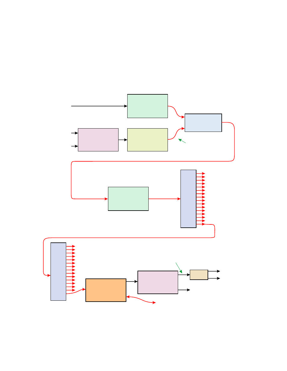
ACCESSORIES AND SYSTEM APPLICATIONS
The OTPN-3850 makes up half of a typical FTTH PON system. The other half is the transmit
hardware. Figure 4 shows a typical configuration of a complete FTTH PON system. The two L-
Band signals are first stacked and then converted to light separately from the CATV signals.
The optical outputs of the CATV and L-Band transmitters are combined by a DWDM Mux and
then amplified by an EDFA. The EDFA output is then split a large number of times and a portion
of that signal input to numerous OTPN-3850’s. The two optical signals from the two
transmitters are added together at the photodiode and decoded as a single 50-3,850MHz RF
signal. The L-Band DeStacker then separates the two original 950-2,150MHz L-Band signals.
Typically the CATV signal is on the same DeStacker output as the L-Band 1 signal.
CATV Tx
e.g. OTOT-1000-FF
or
OTOT-1000-HH
(DWDM Ch 34)
L-Band Tx
e.g. OLAT-X4038
(DWDM Ch 38)
L-Band Stacker
e.g. Global
CATV Signals
50-870MHz
L-Band 1
950-2,150MHz
L-Band 2
950-2,150MHz
2-Channel
DWDM Mux
e.g. OT-DWDM-2
EDFA
e.g. OTEB-CO
or
OTEA-CM
Optical Splitter
e.g. OTCP-1x16
Optical Splitter
e.g. OTCP-1x16
OTPN-3850
Receiver
L-Band DeStacker
e.g. Global
CATV+L-Band 1
50-2,150MHz
L-Band 2
950-2,150MHz
Note: For simplicity, the hardware associated with the Ethernet Signals
usually associated with this type of system are not fully shown.
RF
Optical
Ethernet Equipment
RF
RF
Optical
Optical
Optical
Optical
Optical
FIGURE 4 - Typical System Application Using the OTPN-3850
Diplex
Filter
CATV
L-Band 1
950-2,150MHz
Optical output power is
typically at least 5dB below
the CATV transmitter optical
output power. This may
require an attenuator