Olson Technology OTPT-300 User Manual
Page 7
Page 7 of 8
025-000439 REV A
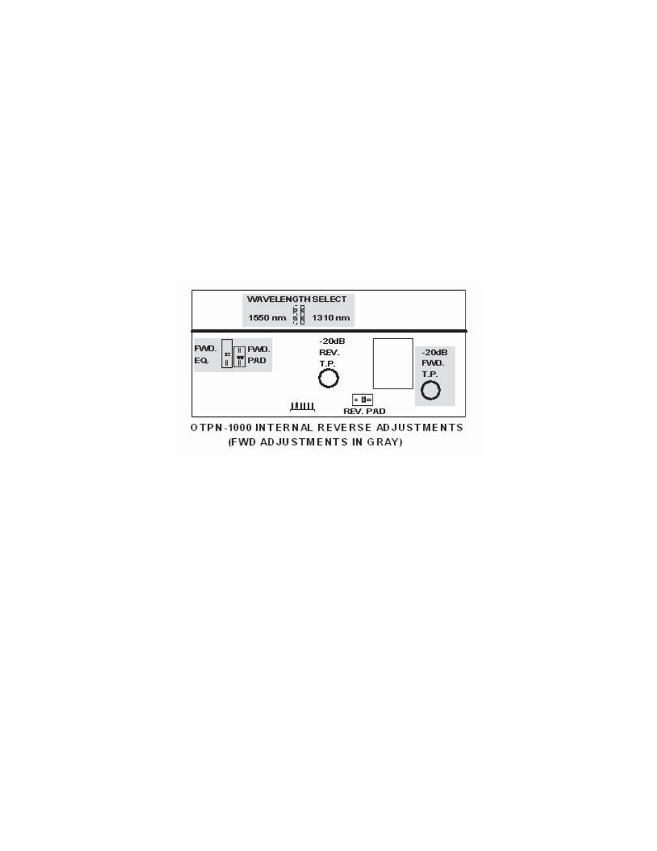
12. The specification for the return band transmitter RF input level is -57dBmV/Hz (measured at the OTPN-1000
R.F. port). This value operates the system at the NPR threshold. The OTPN-1000 has a plug-in attenuator in
the reverse path. Also included is a -20dB test point in the return path. Note that the -20dB test point is before
the plug-in attenuator. The single carrier equivalent of -57dBmV/Hz is +9dBmV. The pad must be selected to
set the return carrier level to +9dBmV actual, after the attenuator. With a test carrier present at the port,
measure its level at the reverse -20dB test point. Use the actual level (test point +20dB) measured, to
determine what value of attenuator must be used to provide +9dBmV after the attenuator.
EXAMPLE:
Test Point reading of +5dBmV plus -20dB test point equals +25dBmV minus +9dBmV equals
16dB pad required.
13.
Firmly replace all OTPN-1000 top cover screws. Failure to do so can result in cooling, RF radiation, or RF
ingress problems.
INTERNAL CONTROLS
There are no internal user adjustments or test points in the OTPT-300. There is no user adjustable internal
laser power adjustment. Any change to the laser power will result in poorer modulation characteristics and reduced
link performance.
The return pad and return test point are located inside the OTPN-1000 as shown above.
EXTERNAL CONTROLS AND TEST POINTS
The OTPT-300 has 2 external DC test points. One reads laser current at 1V per 50mA. A typical laser
current of 25mA would read .5V at this test point. The laser power test point is 1V per mW. This is for historical
tracking. The optical power meter is a much more accurate means of measuring power. Both of these test points
should be measured with a high impedance voltmeter.