Olson Technology OTOHP-RRX User Manual
Page 5
INSTALLATION (CONT.)
FRONT PANEL NUMERIC DISPLAY OPERATION DESCRIPTION
Note: If the power supply turns on after the OTOHP-RRX reverse return path receiver is
inserted, the Display LED will flash for 5 seconds, and indication the receiver is self-
checking.
6
Verify that the correct optical connector will be attached to the optical connector on
the module. Clean both the bulkhead and fiber connectors.
7. Connect the optical fibers to the appropriate OPT IN adapter on the rear panel.
8. Connect the RF cord to the appropriate RF OUT connector on the rear panel.
9. Push the SET button and set the RF TP channels. Using a signal level meter,
measure the RF output at the RF TP test point (20dB below actual level) on the front
panel and verify that it is set at the specified value for that channel. Further adjust
the RF output level if required using MGC function.
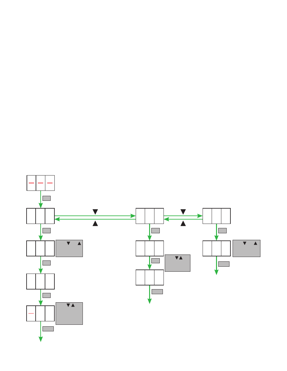
First push SET on the LED display and set function.
.
A01: MGC setting menu
A02: Test Port selection menu
A03: Alarm menu
A0
00
1
1
OFF
A02
0
1
A
0
0
0
3
3
SET
EXIT
Push and
to view
the alarm code.
x
Push and
to set
Port 1 to Port 4
x
Push , and
SET to set the
attenuation
(-20 to 0dB)
Push , and
SET to select
the Port.
SET
SET
SET
SET
SET
EXIT
EXIT
SET