Olson Technology LCM-750x3 User Manual
Page 4
025-000392 REV D
Page 4
2) RF OUTPUT AND AURAL CARRIER LEVEL ADJUSTMENTS
a. Using a field strength meter or spectrum analyzer, set the video carrier to the desired level with the RF
output “level” adjust pot (typically +55dBmV).
b. Tune the field strength meter to the aural carrier, which is located 4.5MHz above the video carrier. Adjust
the aural carrier level control (A/V), to the desired level. This level is typically 15dB below the video
carrier.
3) AUDIO AND VIDEO MODULATION ADJUSTMENTS
a. The video mod adjustment controls the modulation depth. This adjustment is factory set to 80%
modulation. If this adjustment is turned CW the video overmodulation LED will illuminate, turn CCW until
LED just goes off. This is 80% video modulation.
b. The audio mod adjustment controls audio modulation. Again as with the video mod adjustment, the
modulation threshold is factory preset for 50KHz P-P Deviation. Turn adjustment pot CW until audio
overmodulation LED just comes on. Then turn adjustment CCW until LED just goes off. The LED will
flash occasionally during program audio peaks.
c. Stereo Audio operation requires an external BTSC Stereo Encoder such as Leaming Industries model
SG-100. Also, the internal pre-emphasis must be disabled by moving the shunt on J6 from mono to
stereo. (Older versions require cutting the trace at E1 after removing the top cover.)
4) POWER SUPPLY FUSE
There is 1 user replaceable fuse located on the rear of unit. Ensure unit is disconnected from power before
attempting to replace. Replace with 250V/.5A fuse.
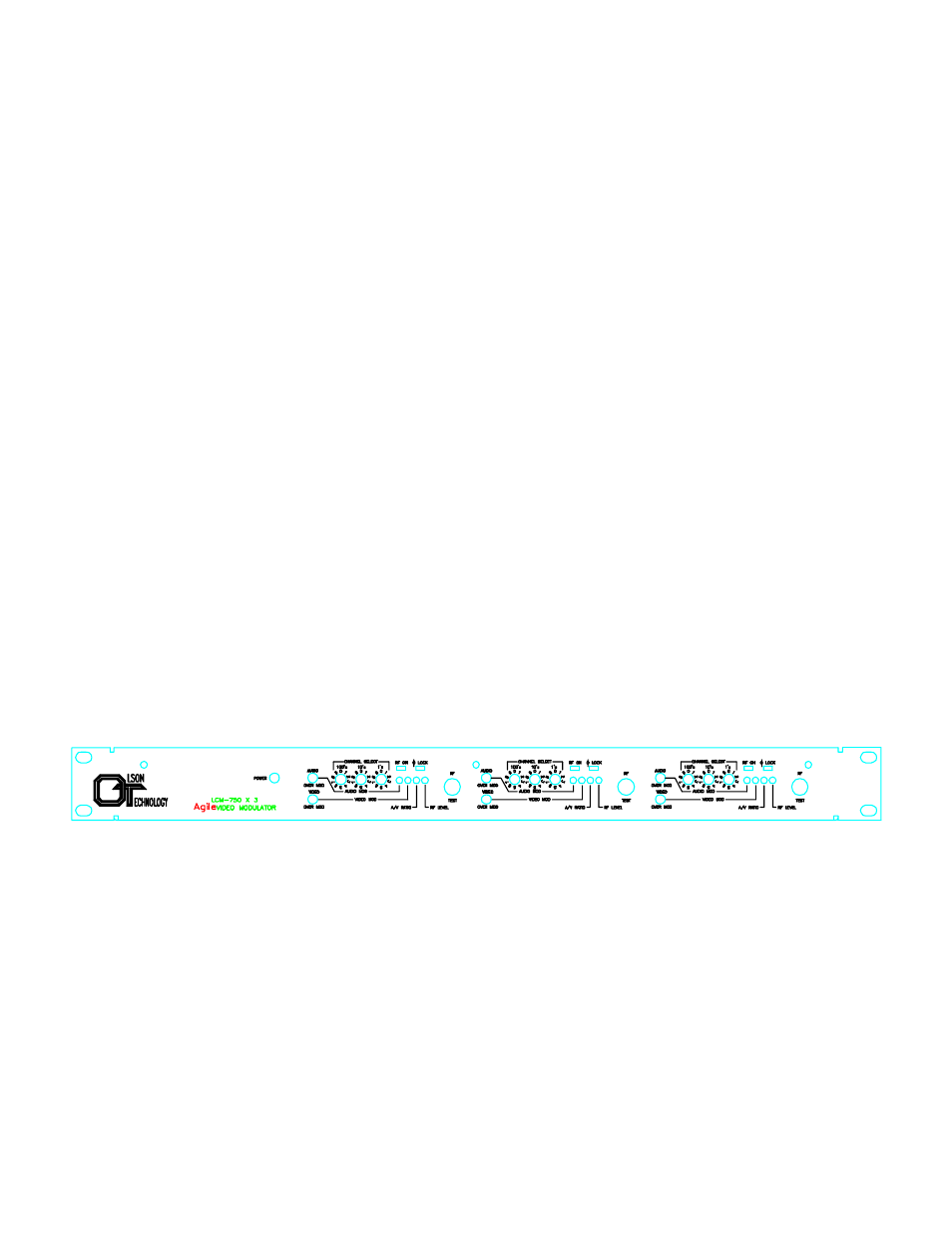
LCM-750 FRONT PANEL VIEW