Olson Technology LCM-300-S User Manual
Page 4
025-370308 REV B
Page 4
2.) CHANNEL SELECTION
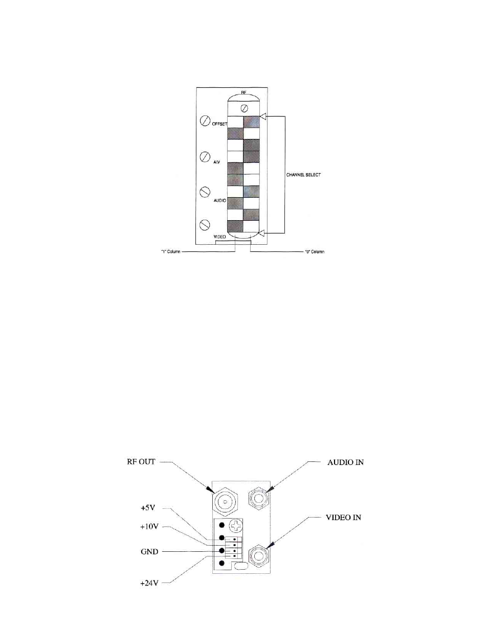
Channel frequencies are selected by setting the 10-position DIP switch (visible through the vertical slot in the
front panel). The front panel is illustrated in figure 1.
Figure 1 – LCM-300-S Front Panel
Switch-setting codes for sub-band channels are shown in Table 1. Switch-setting codes for standard
channel frequencies can be found in Table 2 in this manual, HRC code settings are shown on Table 3. The
front panel illustration in Figure 1 shows a switch properly set for sub-band channel T7.
3.) F.C.C. OFFSET ADJUSTMENT
F.C.C. Offset frequencies are shown in Table 4. To adjust the frequency of a selected channel to provide
the correct F.C.C. offset, look up its offset frequency in Table 4. Remove the video input and connect a
counter to the RF output of the LCM-300-S. Use the front panel offset adjust control to set the output
frequency to the correct value.
4.)
REAR PANEL
The rear panel of each module has its audio and video inputs and its RF output.
The audio and video inputs are RCA type phono jacks and the RF output is a type “F”.