Olson Technology LegacyPlus User Manual
Page 4
025-000480 REV X1
Page 4
INTRODUCTION
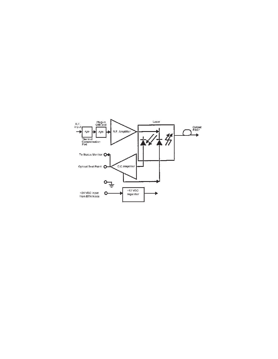
The Olson Technology Inc. AM-MB-RPTDB/SC/302/1 is a high quality, cost effective, Return Transmitter module
designed around the latest optical transmitter technology. It is designed to operate and meet full specifications with
an optical output level of +3 dBm. The transmitter RF path includes a plug-in OMI pad which is preset at the factory for +40 dBmV
carriers. This provides the approved modulation index as reviewed by this customer specific return transmitter varient.
The AM-MB-RPTDB/SC/302/1 recieves preconditioned +24 VDC from the BTN Node and plugs directly into the pre-exsisting
optical lid locations within the Node. RF connections and optical fiber routing are provided inside the optical lid of the BTN Node
already. Heat transfer for the AM-MB-RPTDB/SC/302/1is provided via the bottom surface of the module to the exsisting Node flange
for full outdoor temperature operation.
Heat transfer for the AM-MB-RPTDB/SC/302/1is provided via the bottom surface of the module to the exsisting Node flange for full
outdoor temperature operation.
INSTALLATION / ENVIRONMENTAL CONSIDERATIONS
The AM-MB-RPTDB/SC/302/1 operates with an exterior temperature on the BTN Node of -40 to + 60°C. However, like any other
electronic device, it will probably have a longer life span if it is not operated at the upper limit of it's temperature range continuously.
Installation of the AM-MB-RPTDB/SC/302/1 should be done such that water, dirt and other contaminates do not enter either the
Node or the module. Do not install equipment in locations that are accessible by either children or other unqualified personnel. This
unit is meant to be field-installed into the Motorola BTN Optical Node by qualified field service technicians.
To install the AM-MB-RPTDB/SC/302/1, loosen the 5 of 8 closure bolts on the BTN Node casting enough to rotate the seizure
mechanisms off of the lid of the housing. Open the housing and locate the optical lid as the half clam-shell with the optical
connectors in it. Place the AM-MB-RPTDB/SC/302/1 module into one of the 2 center locations above the back plane, making sure to
orient the 4 position connector on the bottom of the AM-MB-RPTDB/SC/302/1 module in line with the mating connector on the back
plane. Push the AM-MB-RPTDB/SC/302/1 into position firmly, seating the connector. Tighten the 2 captive bolts. Connect the
coaxial RF input cable from the transmitter to an F-81C adapter in the housing lid that is already connected to one of the return output
ports on the forward-return motherboard. Connect the fiber pigtail from the transmitter to a spare optical bulkhead adapter, then
dress the fiber into the fiber spool tray in the lid of the housing. Make adjustments to the RF cable and fiber as necessary. Carefully
close the housing lid while preventing cables and fibers from being pinched. Rotate the seizures onto the housing lid and tighten the
closure bolts per the Motorola specification.