5 mechanical installation – Northern Airborne Technology AMS50 User Manual
Page 22
AMS50-000 Stereo Audio Panel with Marker Manual
SM50 Rev. 4.00
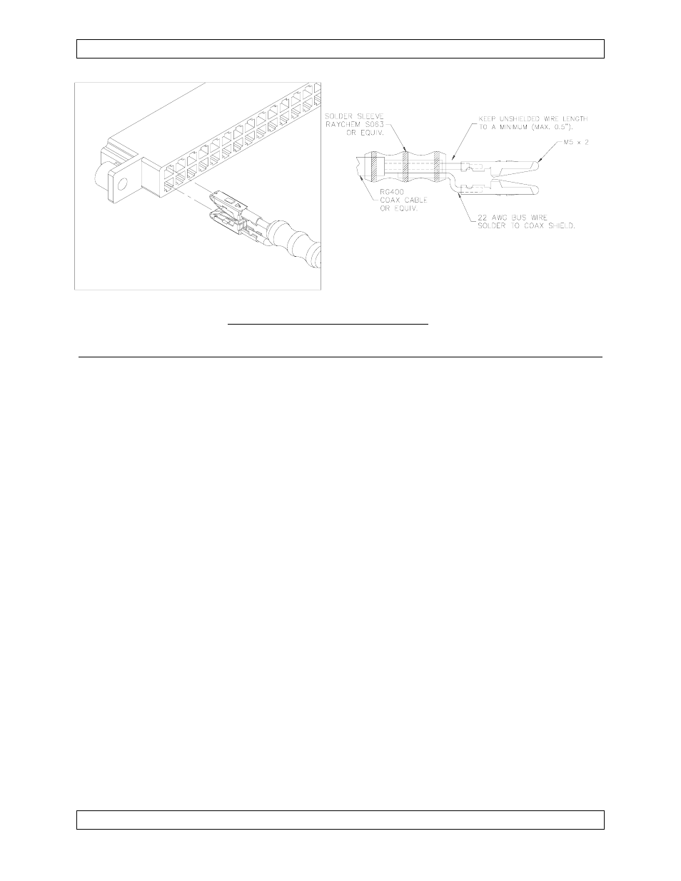
Fig. 2
Marker Antenna Coax Connection
2.3.5
Mechanical Installation
2.3.5.1 The AMS50 may be mounted in any location with adequate area for the front
panel and depth behind the panel for the unit, connector and wiring harness.
Since the AMS50 is shorter than transceivers, the unit is generally mounted
above the radio stack. In installations where the AMS50 is not supported by a
radio stack, it is recommended that the rear of the tray is supported by
brackets (not provided) to the airframe.
2.3.5.2 To mount the AMS50 tray, make a panel cutout using the dimensions shown
in the Mechanical Installation drawing AMS50\000\922-0.
Note: The front lip of the mounting tray must be flush with the front edge of
the instrument panel.
Mark, punch and drill the holes for the mounting rack using the dimensions on
the Mechanical Installation drawing AMS50\000\922-0. Cross-check all hole
positions with the mounting tray. Secure the mounting tray to the instrument
panel using four (4) 6-32 hardware sets (flathead screws, washers and fibre
nuts). Utilize support brackets on the rear of the tray if needed.
2.3.5.3 The AMS50 uses connectors that mate directly with the printed circuit board
inside the unit. They are mounted to the tray using screws supplied in the
install kit. Refer to the installation kit information in Section 2.3.4 for the
correct hardware attachment.
Note: Ensure correct positioning of the card edge connectors (M4) and
polarizing keys (M7) before installing to the AMS50 tray.
2.3.5.4. Slide the unit into the mounting tray until the locking rod contacts the rear of
the mounting rack.
Page 2-4
Nov 12, 2003
ENG-FORM: 805-0104.DOT
CONFIDENTIAL AND PROPRIETARY TO NORTHERN AIRBORNE TECHNOLOGY LTD.