1 left side adjustments, 2 right side adjustments – Northern Airborne Technology N301A User Manual
Page 12
N301A-000 Audio Controller
SM45 Installation and Operation Manual
Section 2 Rev: 1.00
Issue 4
Page 2-5
2.5.1
Left side Adjustments
CVR OUT LEVEL
Adjusts level of the summed received audio, direct audio, and
intercom audio fed to the cockpit voice recorder. Fully ccw is
minimum and fully cw is maximum.
TRANSMIT MIC LEVEL
Six controls (COM1-5, AUX) which adjust the mic output level to
the respective radios. Fully ccw is minimum and fully cw is
maximum.
MODEL (103/105)
A slide switch allows selection of the required variant. With this
switch at position 103, the unit simulates the Andrea A301-103,
and at 105 it simulates the A301-105. (See N301A-000\403-0
interconnect for more details.)
CAUTION:
The MODEL (103/105) switch determines the internal configuration for the
CVR output, and is installation specific. This switch must be set to the
appropriate position to match the wiring configuration in the aircraft. Failure to
set the switch to the correct position will result in no audio being delivered to
the respective recording input on the CVR. Refer to the N301A\000\403
interconnect diagram located in section 2.7 for more information.
2.5.2
Right Side Adjustments
TIE LINE MODE
Selects the tie line option. (see figure 1 below).
ENG-FORM: 805-0117.DOT
CONFIDENTIAL AND PROPRIETARY TO NORTHERN AIRBORNE TECHNOLOGY LTD.
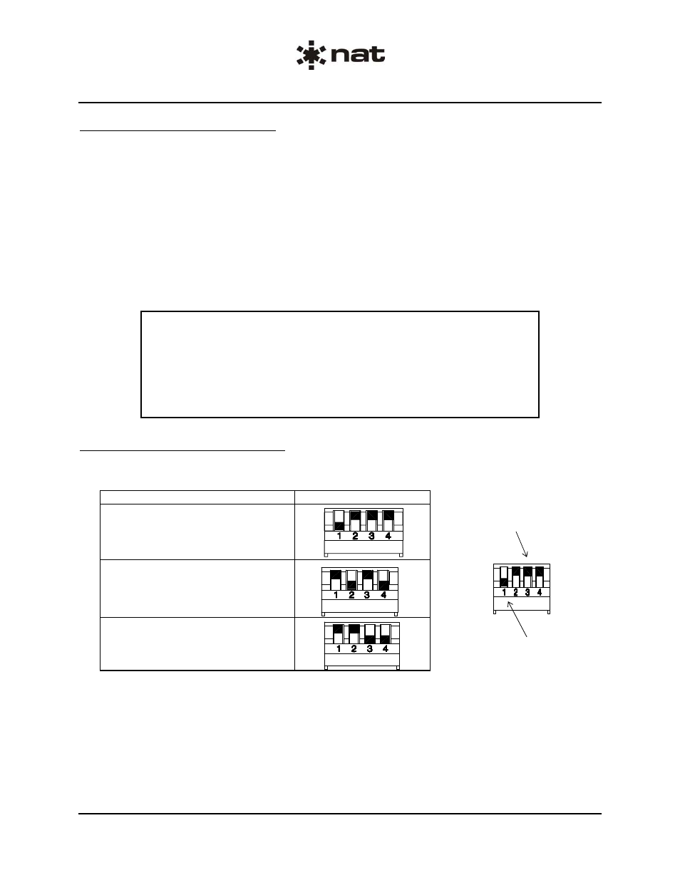
TIE LINE MODE Selection
Switch Positions
ANDREA Tie Lines
1 NAT ICS
2 NAT ICS
Switches 2, 3 and 4
in ‘UP’ position
(Open or Off)
Switch 1 in ‘DOWN’ position
(Closed or On)
Tie Line Mode Switch Configurations - figure 1
a)
ANDREA Tie Lines: TIE LINE MODE switch 1 DOWN, switches 2, 3 and 4 UP
b)
1 NAT ICS Tie Line: TIE LINE MODE switches 2 and 4 DOWN, switches 1 and 3 UP
c)
2 NAT ICS Tie Lines: TIE LINE MODE switches 3 and 4 DOWN, switches 1 and 2 UP