NIStune Type 5 User Manual
Page 10
Type 5 Hardware Installation Manual
Page 9 of 15
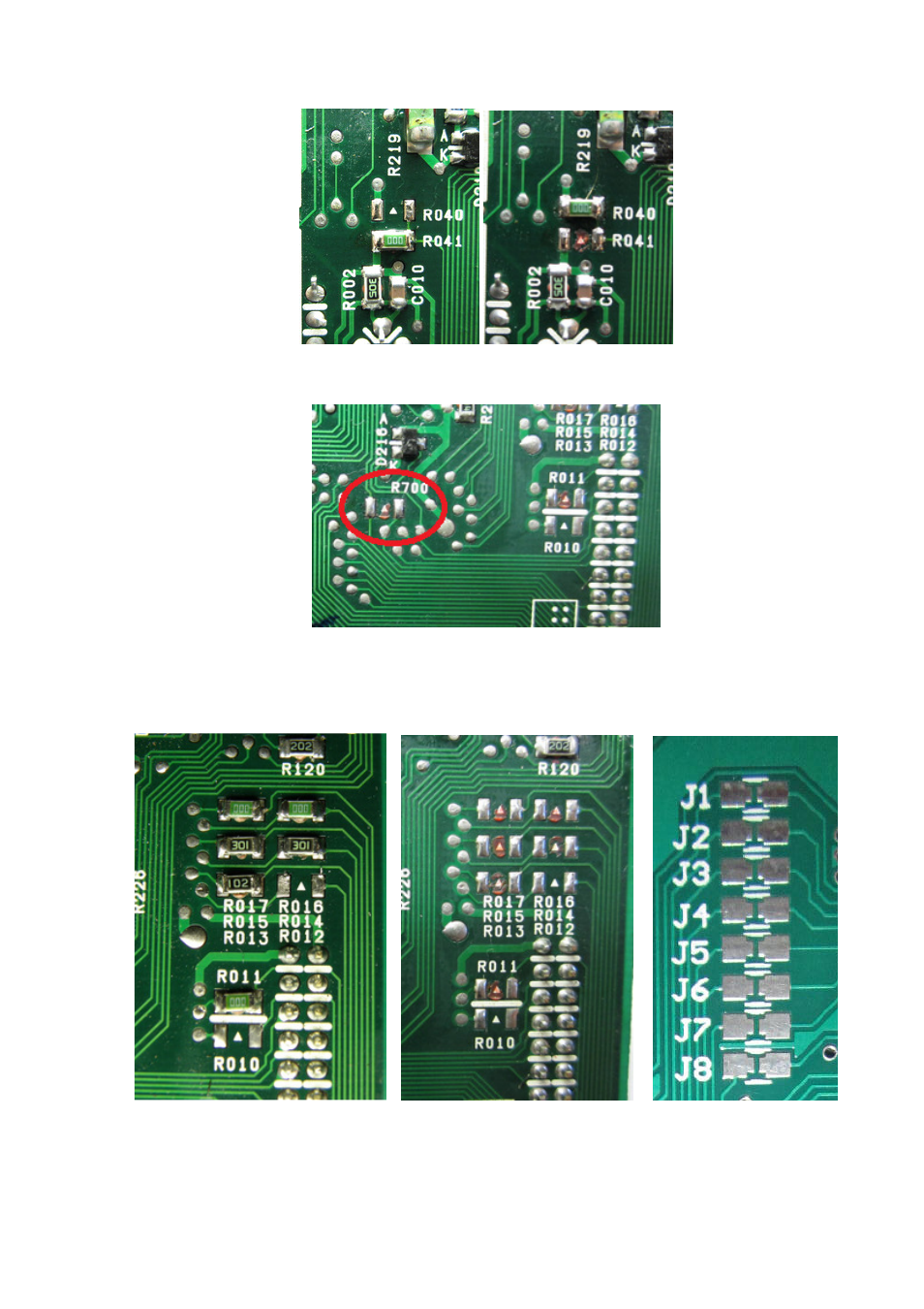
• S14 SR20DE 180SX (65F00 MT only), N15 GA16DE Pulsar/Sunny, B14 Sentra GA16DE ECU
Move jumper R041 to R040
Remove jumper R700
Move resistors R010 - R017 from ECU to J1-J8 on the Nistune Type 5 board using a soldering
iron and tweezers. Make sure both ends are soldered when putting on the Nistune board. Use
flux to assist solder flow with the SMD resistors.
Notes:
S14 SR20DE (65F00 MT model only, 74F10 AT does not support this board)
J1 = Open, J2 = 000, J3 = Open, J4 = 102, J5 = 301, J6 = 301, J7 = 000, J8 = 000
N15 GA16DE, B14 SR20DE
J1 = Open, J2 = 000, J3 = 301, J4 = 102, J5 = 301, J6 = Open, J7 = 000, J8 = 000