2 other dip switches – Nevion AAV-HD-DMUX User Manual
Page 12
AAV-HD-DMUX(-R)/ AAV-SD-DMUX(-R)
Rev. 7
nevion.com | 12
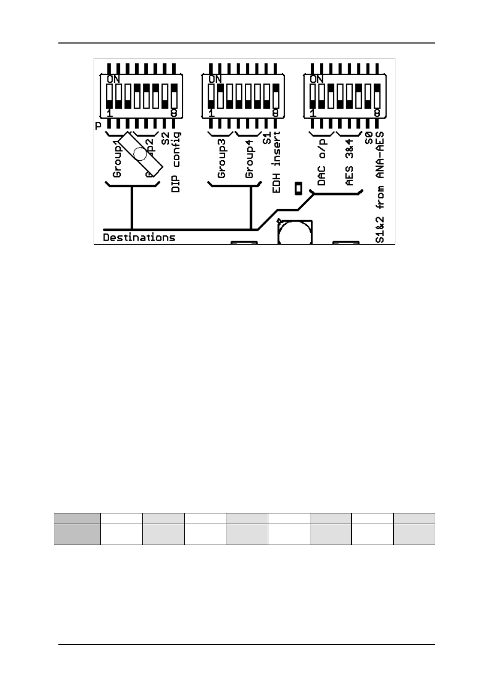
Figure 4: Example 2
The module above (Figure 4) is set to the following:
Group1 output is not embedded
Group2 output is embedded with a stereo tone from the internal generator
Group3 output is embedded with signals from de-embedded group 2
Group4 output is not embedded
Analog DAC outputs signals from de-embedded group1
AES 3&4 outputs signals from de-embedded group1
Users familiar with binary numbers may see that source numbers 1 to 4 (001 to 100)
correspond to groups 1 to 4. Binary numbers 5 (101) and 6 (110) are not used on this
module.
3.2 Other DIP Switches
3.2.1 DAC converter gain, SW1.7, SW2.7 and SW3.7
The DAC convert output levels may be set to one of the eight preset levels with the DIP
switches. The analog levels correspond to the maximum sine wave level, otherwise known
as 0 dBFS. The three switches are labeled S2, S1 and S0 on the board. The combinations of
the three switches set up the output level as shown in the table. 0 is off or down, 1 is on or
up.
S2,S1,S0 000
001
010
011
100
101
110
111
Level
(dBu)
+12
+13.5
+15
+16.5
+18
+20
+21
+24
All four input levels are set by the DIP switches in DIP configuration mode. GYDA can set the
levels for each channel individually.
3.2.2 DIP Configuration, SW1.8
SW1.8 on, forces the DIP switch configuration to be used. If there is a GYDA present, the
switch configuration on the module will be used and the configuration will be just be
monitored in the GYDA controller.