Fig. 7, Fig. 8, Fig. 5 fig. 4 – MovinCool CMW30 User Manual
Page 2: Fig. 6
3
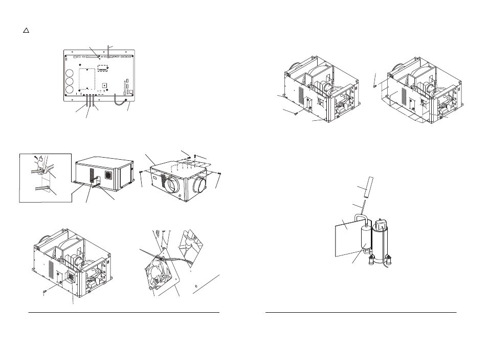
2- 6. Remove four (4) screws and loosen two (2) bottom screws. Remove eleven (11) screws, and
then remove the rear panel (see Fig. 7).
Screws (4)
Bottom Screw (1)
Bottom
Screw (1)
Screws (11)
Rear Panel
Fig. 7
2- 7. Remove the insulators from tube 1 and accumulator, then braze tube 1 and recover the
refrigerant (see Fig. 8). Note: Refer to the CMW30 service manual for the brazing detail
and refrigerant handling.
Fig. 8
Tube 1
Insulator B
Insulator A
Accumulator
2
2-3. Disconnect CN103, CN104, CN105, and CN7 wires from the relay board (see Fig.4).
Fig. 5
Fig. 4
WARNING: Do not touch the relay board until the green LED#7 is turned off. Failure
to follow this warning may lead to electrical shock.
!
CN18
CN17
CN19
CN20
CN21
CN6
CN8
CN10
CN7
CN9
CN
11
CN5
LED1 LED2 LED3 LED4 LED5 LED6
CN12
CN13
CN14
CN4
CN2
CN3
CN1
CN106
CN107
CN7 Wire
CN105 Wire
CN104 Wire
CN103 Wire Relay Board
CN103
CN101
CN102
CN104
CN105
LED #7
2-4. Disconnect the water inlet and outlet pipes from the unit and then remove twenty one (21)
screws to take off the unit’s top panel (see Fig. 5).
Screws (5)
Screws (6)
Top Panel
Screws
(
4
)
Water Outlet Pipe
Water Inlet Pipe
Screws(6)
Wrench A
Wrench B
NPT Connector
2-5. Remove four (4) screws and remove the AC fan motor. Then disconnect two (2) connectors
from the AC fan motor (see Fig.6).
AC Fan Motor
Screws (4)
Connectors (2)
Fig. 6