Installation, Continued optional mantel installation – Desa EFS10TNA User Manual
Page 13
www.desatech.com
112462-01G
13
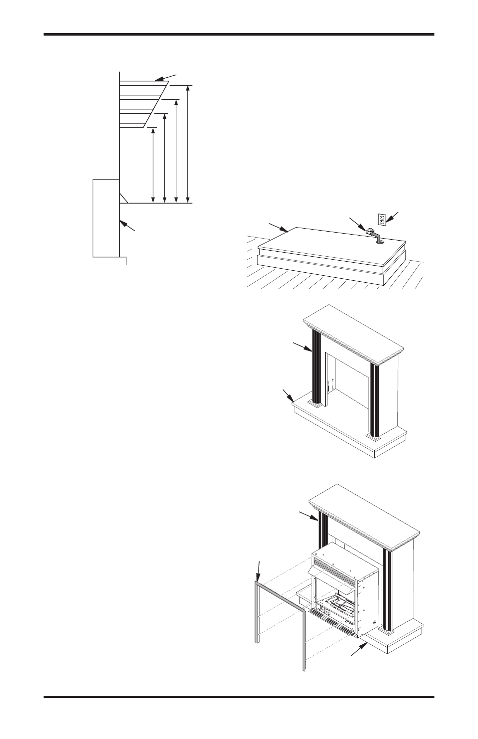
Mantel Shelf
13"
16"
19"
21"
2
1
/
2
"
6"
8"
10"
Note:
All vertical
measurements
are from top of
fireplace
opening to
bottom of
mantel shelf. All
measurements
are in inches.
Figure 10 - Minimum Mantel Clearances
for Built-In Installation
iNsTallaTioN
Continued
OPTIONAL MANTEL INSTALLATION
Refer to instructions provided with the mantel
for assembly instructions. Refer to the follow-
ing instructions for system installation. Refer to
instructions on page 6 for hood assembly. Blower
accessory should be installed prior to mantel if it
is being used (see Installing Optional Blower Ac-
cessory GA3450TA, page 14).
1. Assemble cabinet mantel as shown in acces-
sory instruction sheet.
2. If blower is installed, install a properly
grounded, 120 volt three-prong electrical out-
let at fireplace location if an outlet is not there.
If possible, locate outlet so cabinet mantel will
cover it when installed (see Figure 11).
3. Place hearth base against wall at installation
location. Cut an access hole in hearth base to
run gas line to fireplace (see Figure 11). Make
sure to locate access hole so cabinet mantel will
cover it when installed. Note: You can secure
base to floor using wood screws. Countersink
screw heads and putty over.
4. Route flexible gas line through access hole in
hearth base.
5. Center cabinet mantel on hearth base (see
Figure 12). Make sure mantel is flush against
wall and centered left to right on base.
6. Use screws provided with mantel accessory
to attach mantel assembly to base (see mantel
instruction sheet).
7. Attach flexible gas line to fireplace gas regula-
tor. See Connecting to Gas Supply, page 17.
8. Route electrical cord(s) through access holes
in either side of fireplace with bushing. Plug
electrical cord(s) into electrical outlet.
9. Check all gas connections for leaks. See
Checking Gas Connections, page 19.
10. Carefully insert fireplace into cabinet mantel
(see Figure 13). Be careful not to scratch or
damage hearth base or cabinet mantel.
11. Place metal trim on shoulder screws located
on the side and top of the fireplace (see Assem-
bling Perimeter Trim, page 14). Firmly snap
trim over shoulder screws. Align fireplace in
mantel assembly so the trim overlaps mantel
evenly on all three sides.
12. Lower bottom louver door. Use 3" wood screws
provided with mantel accessory to attach fire-
place to base (see mantel instruction sheet).
Side of Firebox
Figure 11 - Placing Hearth Base Against Wall
Hearth
Base
Electrical
Outlet
Pipe and Gas
Shutoff Valve
Figure 12 - Installing Cabinet Mantel onto
Hearth Base
Cabinet
Mantel
Hearth
Base
O
F
F
P
ILO
T
O
N
H
I
L
O
Figure 13 - Installing Fireplace into
Mantel Assembly
Cabinet
Mantel
Assembled
Trim
Hearth Base