Ssa-50, Definitive technology, Owner’s manual – Definitive Technology Mythos Solo Surround Array SSA-50 User Manual
Page 3: Wall mounting the ssa, Positioning the ssa, Mounting the ssa to an articulating tv bracket, Using the leveling feet, Connecting the ssa, Subwoofer, Receiver
Definitive Technology
SSA-50
OWNER’S MANUAL
5. Use a bubble level to make sure the template is level. If the
TV is wall mounted and not level, the speaker will look better
if it is off-level in exactly the same way as the TV.
6. Use push pins to secure the template to the wall.
7. Mark the location of pilot holes noted on the Mounting
Template with a pencil; remove the template.
8. Pre-drill the pilot hole locations for mounting screws
(not included). Use screws rated to hold securely in the
wall material (we recommend #10 screws).
9. It is best if at least one screw hits a wall stud. If there is no
stud behind the pilot hole location, install wall anchors (not
included) to secure the bracket screws. Follow the wall anchor
manufacturer’s directions. Each wall anchor should be rated
to hold at least one-half of the product net weight
[see specifications on front cover].
10. For masonry walls, use a masonry drill bit to pre-drill holes,
and use masonry anchors and screws (not included).
11. Pull the five sets of speaker wires through the hole in the bracket.
12. Screw the bracket to the wall.
Wall Mounting the SSA
•
We recommend that the SSA speaker be wall mounted
by professional installers or by those appropriately skilled in the
use of power tools and who have knowledge of building codes
and structural issues.
•
We recommend that you determine a suitable location for
your speaker installation, and that you complete all wiring
(especially “hidden” in-wall wiring) before mounting the
bracket to your wall.
•
Mythos Brackets are not suitable for ceiling mounting.
The Mythos Solo Surround Array loudspeaker comes with a wall
mounting bracket and template that makes secure mounting a breeze.
Follow these directions for installing the wall mounting bracket.
1. Two
1
⁄
4
"–20 screws have been factory installed on the back of the
speaker. Gently hand-turn the screws to make sure they are in as
far as they can go. Do not force them beyond the “stop” point.
The screws cannot screw all the way into the speaker and should
protrude as shown in the illustration.
2. Make sure the location you have selected for wall-mounting
does not conceal behind-wall electrical wiring or plumbing.
3. Hold the cardboard template (included) in the intended
location. Make sure the speaker clears the ceiling, adjacent
walls, corners, beams, lighting fixtures and door/window
frames. Leave at least 1
1
/
2
" (38 mm) above the speaker location
to allow the speaker to slide down onto the bracket.
4. Make sure the center of the template is perfectly centered with
the TV screen.
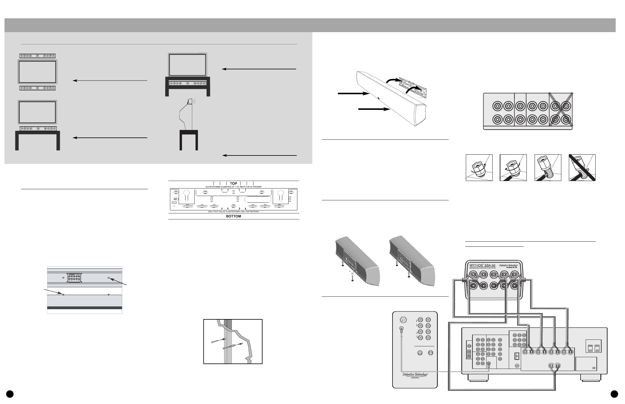
Positioning the SSA
The SSA speaker may be mounted on
the wall above or below the video screen.
It may be placed on a table or shelf
in front of the TV.
If placed on a shelf under a TV, adjust the
leveling feet (screwed all the way in) to
aim the speaker up towards the listeners.
The SSA speaker may be placed directly
on top of TVs that have at least 5-inches
(13 cm) of flat surface on top. Do not
place the SSA speaker on top of any
surface that is not large or stable enough
to securely support the speaker. If the
speaker seems at all unstable or “tipsy”
place the speaker somewhere else. The
warranty does not cover damage
caused by falls due to improper
positioning of the speaker. If the
speaker is above seated listener height,
extend the leveling feet to point the
speaker downward [See Using the Leveling
Feet on page 3].
13. When the wall mounting bracket is securely screwed to the wall, line
up the speaker’s protruding Mounting Screws with the keyhole slots
on the wall mounting bracket. Let the speaker slide straight down,
allowing the screw heads to slip behind the smaller end of the keyhole
slots. Gently push the bottom front edge of the speaker toward the wall
until the speaker snaps onto the lower lip of the bracket.
Mounting the SSA to an articulating TV bracket
If you have a Plasma or LCD TV that is attached to the wall via a
swing-out articulating bracket such as those offered by Chief, Sanus
and OmniMount, the SSA speaker may be attached to the bracket
without using the SSA wall-mount plate. Simply use
1
⁄
4
"–20 screws to
attach the SSA speaker directly to the TV bracket. Consult the TV
bracket manufacturer’s user manual for more specific speaker
mounting instructions.
Using the Leveling Feet
If you are going to use the speaker on a TV, shelf or table, first attach
the wall-bracket to the speaker as described above. Attach the two “L”
brackets to the wall-bracket using two M4 x 10 mm screws provided.
Thread the foot screws into the two “L” brackets and adjust to the
required height.
Connecting the SSA
Your Mythos SSA has one pair
of 5-way binding posts for each
channel — Left Front, Right Front,
Center, Left Surround
and Right Surround.
To start, strip
1
/
2
" (3 mm) of
insulation from each speaker
wire to expose the bare metal
wire and twist each of the
individual conductors into
single un-frayed strands.
Note that one of the terminals for
each channel is marked with red
band (+) and the other is marked
with black band (–). Make certain
that you connect the wire from the
red (+) terminal of your amplifier
or receiver to the red (+) terminal on your speaker and the wire from the
black (–) terminal of your amplifier or receiver to the black (–)
terminal on your speaker. Most speaker wire has some indicator (such as
color-coding, ribbing or writing) on one of the two conductors to help you
maintain consistency. It is essential to connect all channels
of the speaker to the amplifier in the same way (in phase). If you
experience a poor surround effect, it is likely that one or more of the chan-
nels is connected in incorrect polarity and needs to be rewired.
Pay close attention and connect positive to positive; negative to
negative on all channels.
If you have a 6.1 or 7.1 channel receiver, connect the SSA’s surround
channel inputs to the “Surround” outputs of your receiver, not the
“Rear” or “Surround Back” outputs.
To connect wire to the binding post [see figure above], unscrew the knurled
nut and insert the bare wire into the hole near the base of the binding
post. Do not insert the insulated part of the wire into the hole as this will
not give you a good connection. Twist the nut back down the binding post
until it firmly meets the wire. Do not over tighten.
Connect a single RCA cable from the “SUB OUT” of your receiver
to the LFE input of the subwoofer (not included). This connecting
method bypasses the subwoofer’s internal “crossover” or low pass
filter and relies on the crossover filter built into your receiver.
NOTE: Make no other signal connections. Do not use speaker wire to make
the connection to the subwoofer
SSA-50
OWNER’S MANUAL
SSA-50 Mounting Screw Diagram
BACK OF SPEAKER
TOP OF SPEAKER
1
/" –
4
20 SCREWS
THREADED INSERTS
SUBWOOFER
95
150
40
Variable
Low Pass Crossover
120V 80Hz
T 3.2A L 250V
Automatic
Power
ON/OFF
P roC ine ma
S ubw o ofer
A cti ve Cr o s so ve r
a nd Pow er A mpl i fier
High Level
+
+
–
–
Left
Right
®
LFE
IN
In
Out
RECEIVER
AUDIO
AUDIO
MULTI INPUT
SUBWOOFER
(LFE)
OUTPUT
COMPONENT VIDEO
FRONT LEFT
FRONT RIGHT
SURROUND RIGHT
CENTER
SURROUND LEFT
IMPEDANCE SELECTOR
VIDEO
SSA-50
FRONT
RIGHT
CENTER
+ –
+
–
+ – +
+
–
–
+ –
SURROUND
RIGHT
FRONT
LEFT
SURROUND
LEFT
2
SSA-50 Mounting Template Revised
SPEAKERS
FRONT
RIGHT
+
–
LEFT
RIGHT
LEFT
CENTER
SURROUND
RIGHT
LEFT
SURR. BACK/REAR
FT
R
RIGHT
S
3
Even if you intend to place the SSA speaker on a TV or shelf you must attach the wall-mount bracket to the speaker. See Using the Leveling Feet on page 3.