System example, Operational details set up stacking, 1 channel installation – Memphis 16SC2120 User Manual
Page 2: 2 channel installation
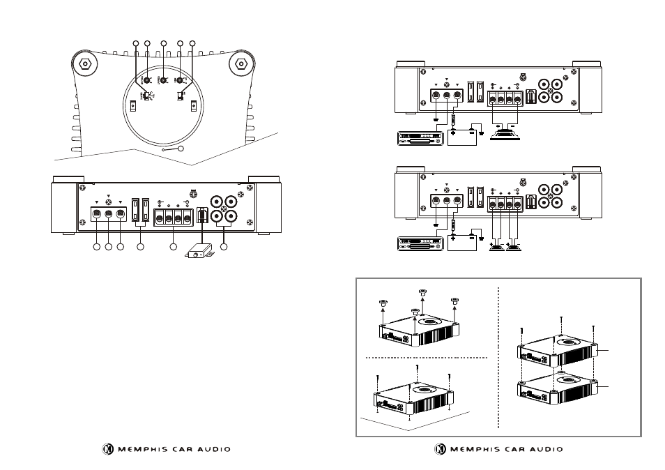
System Example
2 Channel Power Amplifier
SC 2.120
Operational Details
Set up Stacking
Top Cap
Tapping Screw
(M4 X 20)
Self-Tapping Screw
Second Unit
First Unit
(M4 x 20)
1 Channel Installation
GND
FUSE
25A
25A
FUSE
L
BRIDGE MODE
SPEAKER
R
REMOTE
LPL
OUTPUT
INPUT
R
L
+12V
RMT
Bridge Mode
Bridge Mode
2 Channel Installation
GND
FUSE
25A
25A
FUSE
L
BRIDGE MODE
SPEAKER
R
REMOTE
LPL
OUTPUT
INPUT
R
L
+12V
RMT
GND
FUSE
25A
25A
FUSE
L
BRIDGE MODE
SPEAKER
R
REMOTE
LPL
OUTPUT
INPUT
R
L
+12V
RMT
1
2
3
4
5
6
Remote
Remote
Control
Control
(1)RCA INPUT : Connect these RCA connectors to a head unit with a LOW LEVEL output connection.
RCA OUTPUT: Use these RCA output connectors to connect to a secondary amplifier.
(2)SPEAKER OUTPUT
See installation diagram in this manual for correct speaker connection.
(3)FUSES : Please ensure correct type of fuse is fitted.
(4)+12V INPUT
This must be connected to the vehicle battery positive(+) terminal via correct power cable and with an inline fuse or circuit breaker
at the battery end. NOTE : This is to be the last wire connected during installation, as damage could result.
(5)REMOTE INPUT
This terminal is for turning the amplifier on and off. This requires a switched positive (+)12V to power 'ON' the amplifier, this can be
found on the rear of the head unit in the form of an electric antenna output, or a remote turn-on output. If not available you can wire to the
ACC position on the key.
(6)GROUND INPUT
Connect directly to the vehicle's chassis via correct cable. NOTE : This is to be the first wire connected when wiring up the
amplifier, as damage could result if this is not done.
(7)CROSSOVER SELECTOR
Set the appropriate mode of operation. The 3 positions available are OFF, LP and HP.
(8)SUBSONIC FILTER
This is a selectable switch that filters out 20Hz and below 12dB/octave.
(9)HIGH PASS
Set the crossover switch to HP and turn this control to 65Hz or above when using speaker's smaller than 6 x 9", this feature
is designed to filter out all low bass frequencies that only SUBWOOFERS should produce.
(10)LOW PASS
Set the crossover switch to LP when a subwoofer is connected. Ensure the crossover frequency is set at 100Hz or below.
(11)LEVEL (GAIN)
This allows level adjustment of the input signal. Use this control to correctly match the amplifier. To set this control correctly,
turn the amplifier level to MIN and the head unit to 3/4 volume, with the BASS and TREBLE on zero, then slowly turn up this amplifier
level control towards towards the MAX end of the control. NOTE : If the sound becomes distorted, turn this control down.
(12)POWER, STATUS AND THERMAL LED's
This shows if the amplifier has been correctly powered up and if any faults are present.
S
U
B
S
O
N
IC
2
0
H
z
5
0
H
z
5
0
H
z
2
5
0
H
z
2
5
0
H
z
12
9
9
8
8
10
10
11
11
7
7