MEGA Corp. MHT175-CAT777-INSP-RSP-5 User Manual
Page 12
3-1
MHT175-CAT777(G)-5
4 Feb 2014
SECTION 3
Special Inspections
Contents
DESCRIPTION
This section contains special inspection requirements
for exceeding an establish system limit. The
established inspections are designed to reveal any
damage sustained and determine serviceability of
the MHT175 system.
TURN LIMIT INDICATOR CONTACT
The metal turn limit indicator is designed to provide
a visual indication to the operator they have reached
the maximum rotation of the MHT. This is noted by
the gooseneck cheek contacting the turn limit
indicator as shown below.
When the system experiences high impact loads
damage may occur to both the gooseneck cheek
plates and the turn limit indicator. The gooseneck
cheek plates may buckle or begin to weaken and
eventually cause further damage to adjoining
gooseneck plate structure. The turn limit indicator
may experience excessive bending moments and
begin to tear or weaken lower mount plate and horse
collar welds.
INSPECTION
1. Remove a gooseneck access cover.
2. Check gooseneck cheek structure for damage.
Inspect welds for evidence of cracking and metal
plates for signs of buckling.
3. Check adjoining gooseneck interior and exterior
structure for damage. Inspect gooseneck
structure and plating for weld cracking and
evidence of steel plate buckling.
4. Check turn limit indicator for damage. Inspect
plates and welds for cracks and deformities.
5. Check turn limit indicator deck and horse collar
mounts for damage. Inspect rail mounting plates
and angle brackets for cracks and loose hardware.
Contact MEGA Product Support at: 1-800- 345-8889
for any major structural repair issues.
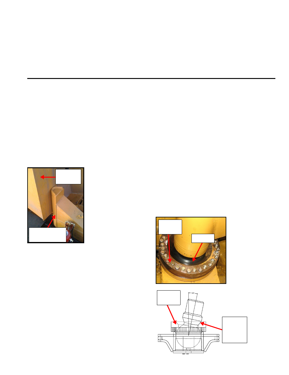
HITCH BALL OVER OSCILLATION
The hitch ball assembly is designed to oscillate 12
degrees within the lower socket assembly as shown
below. This allows the MHT175 a large range of
motion when operating in the pit, on haul road, on
coal piles and when unloading the trailer (MHT).
Gooseneck
Cheek
Metal Turn Limit
Indicator
Retention
Plates
Ball Hitch
12
Retention
Plates
Ball to
Retention
Plate
Contact
Hitch Ball Over Oscillation ............................................3-1