LSC Lighting iPatch User Manual
Page 3
LSC Lighting Systems (Aust) Pty Ltd
Page 2
iPATCH Installation guide
1.0 Introduction
The iPATCH performs the power cable patch interface between installed lighting fixtures and
the dimming equipment controlling the fixtures. Each patch circuit is internally wired and has
a 1.5metre flexible lead fitted with a Australian 3 pin piggy back plug.
Extra patch circuits can be added at any time after installation (space permitting) to increase
the total number of patch circuits. Four cable knockout holes are provided in the rear chassis
for cable entry/exit.
The iPATCH has a removable front cover which contains a test circuit for testing of fixture
loads on the patch circuits. The iPATCH is available in two chassis sizes;
•
iPATCH 48; available with a minimum of 24 circuits, increasing in 6 circuit increments to a
maximum of 48 circuits.
•
iPATCH 72; available with a minimum of 54 circuits, increasing in 6 circuit increments to a
maximum of 72 circuits.
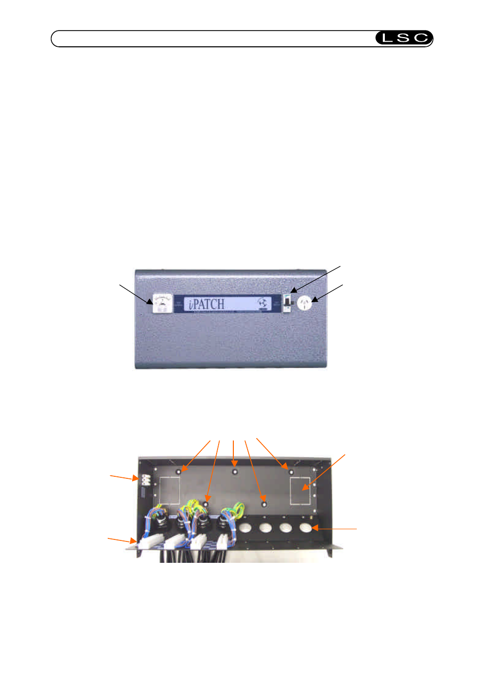
iPATCH front cover
Load test socket
Load test ammetert
Load Circuit Breaker
iPATCH rear chassis
iPCH/24 shown
Mounting holes
Cable knockouts
Holes for extra
circuits
Test circuit power
connector
Load wiring
terminal strips