Lacava llc 4 – Lacava 1842 User Manual
Page 4
LACAVA LLC
4
Installation Instructions/Instrucciones de Instalación
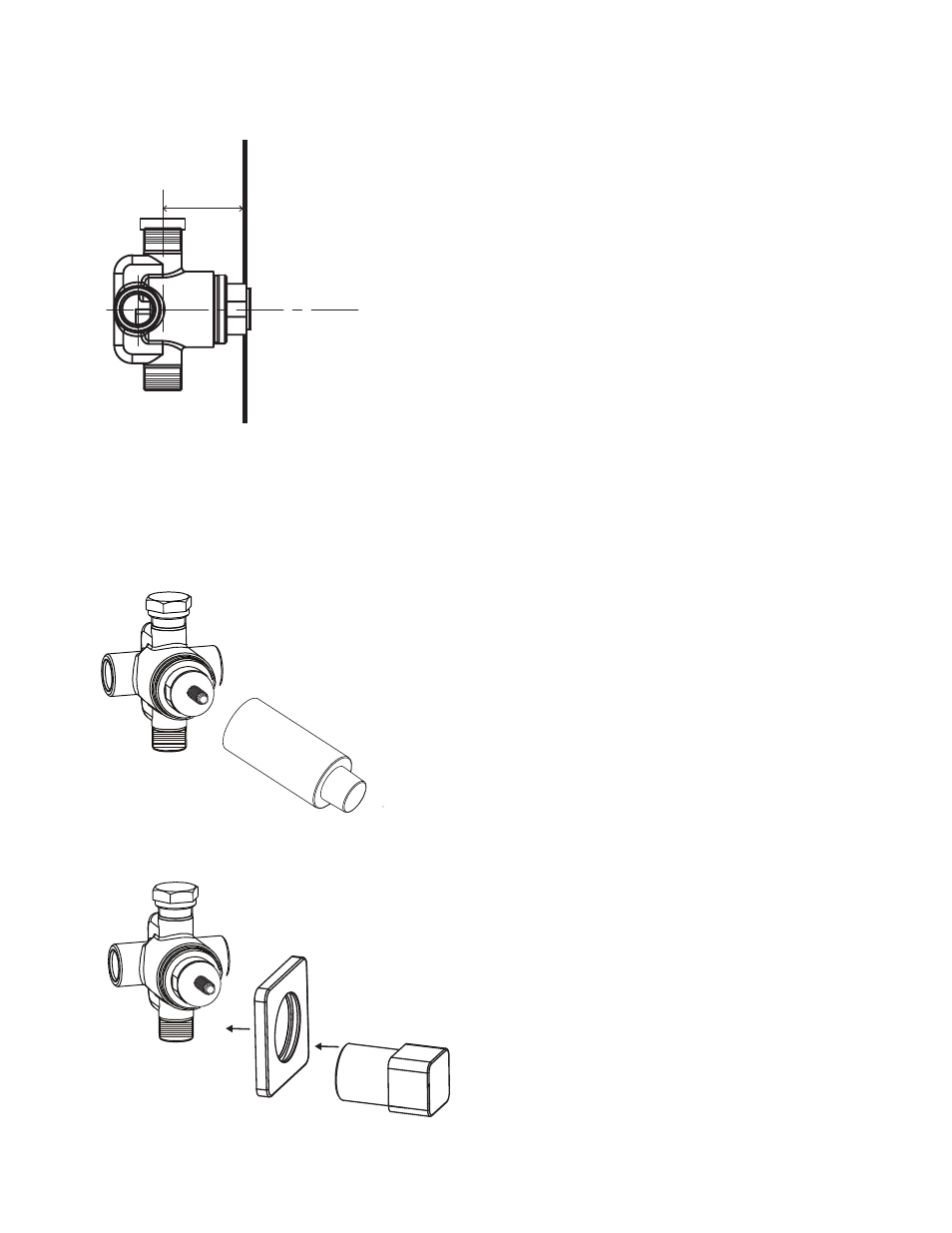
1. Determine the location of the valve making sure that the
center line of the valve is located 1 5/8” - 2 3/8” from the surface
of the finished wall.
2. Once proper location is determined, install supportive framing
to mount valve by using included screws.
3. Install NPT threaded copper adapters to the inlet & outlets,
applying teflon tape to all threaded connections.
Then solder copper piping onto adapters and run to
designated water supply or outlet.
Important! Take the following precautions if soldering copper
piping directly onto valve:
a.) Remove ALL components from the valve prior to soldering,
including plaster guards & cartridges.
b.) Wrap valve body with cold rag before soldering. Take
special care not to overheat brass rough-in.
c.) Use copper piping only, do not attempt to solder steel
piping to valve.
d.) Reinstall all components after soldering.
4. Make sure all functions are plugged or in the off position.
Then turn water on and bleed air from lines. Inspect all piping
for leaks. Make sure to inspect complete system by diverting
water to all functions.
7. Slide escutcheon (A) over the cartridge and up against
the wall. Silicone may be used to seal the escutcheon
to the wall.
8. Now thread the handle assembly (B) onto the rough valve.
5. Finish the surrounding wall. To ensure proper fit, do not over-
size the hole - use the plaster guard as a guide for correct
diameter.
6. Remove the plaster guard once the finished wall is complete.
1 5/8" - 2 3/8"
42 - 62
FINISHED
WALL
A
B