Kleenmaid RH12 User Manual
Page 4
3
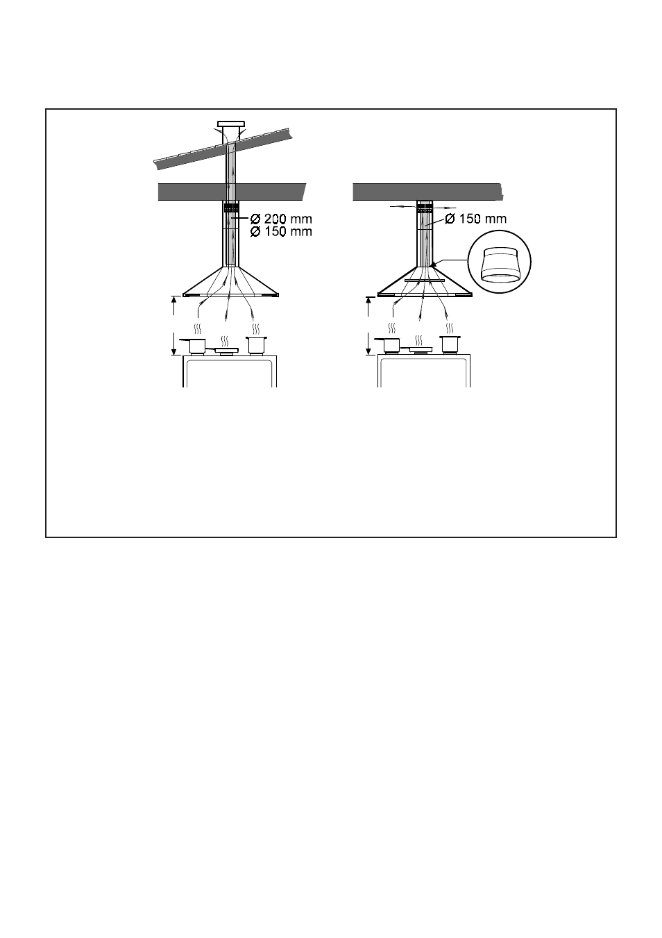
Exhaust mode
Recirculation mode
Key
B: Reference mark on the upper side of the telescopic
A: For extractor version
on the right).
structure, indicating the front of the hood (control panel
F: For filter version only.
C: Location for hood connection box.
of the telescopic structure (operation 1):
How to calculate the MAXIMUM ALLOWED extension
to the hob;
a)measure the distance (in millimeters) from the ceiling
combination hobs; for electric hobs subtract 1100
b)subtract 1000 mm from this measurement for gas or
c)the measurement obtained is the MAXIMUM extension
mm;
of the telescopic structure.
See also other documents in the category Kleenmaid Hoods:
- RHSGFOCUS (11 pages)
- RHSGALA (11 pages)
- ARTICA (12 pages)
- ANTARTICA (12 pages)
- RHSGSPOT (18 pages)
- OPTICA90 (23 pages)
- BOXISLAND120 (19 pages)
- AURORA90 (30 pages)
- BOX120 (24 pages)
- EMPIRE (12 pages)
- CONCAVE (12 pages)
- SPOT120 (12 pages)
- SPOT120 (12 pages)
- K120 (16 pages)
- TAMAYA90 (12 pages)
- HALFFRAME90 (31 pages)
- MINI OM (8 pages)
- MENHIR (12 pages)
- SAMURAI (12 pages)
- RH3X (8 pages)
- RH3A (7 pages)
- RH5 (8 pages)
- TONDA90 (34 pages)
- RH5X (12 pages)
- RH8 (8 pages)
- RH22 (8 pages)
- RH22 (9 pages)
- RH15 (10 pages)
- RH16 (12 pages)
- RH23X (7 pages)
- RH24W from August 2008 (12 pages)
- RH13 (24 pages)
- RH30 (8 pages)
- RH90 (12 pages)
- RHCBB90 (12 pages)
- RHWMDB40 (16 pages)
- RHU60 (10 pages)
- RHSOTF90 (14 pages)
- RHMC120 (16 pages)