4 welding and earth cables – Kemppi KMS 300 User Manual
Page 9
EN
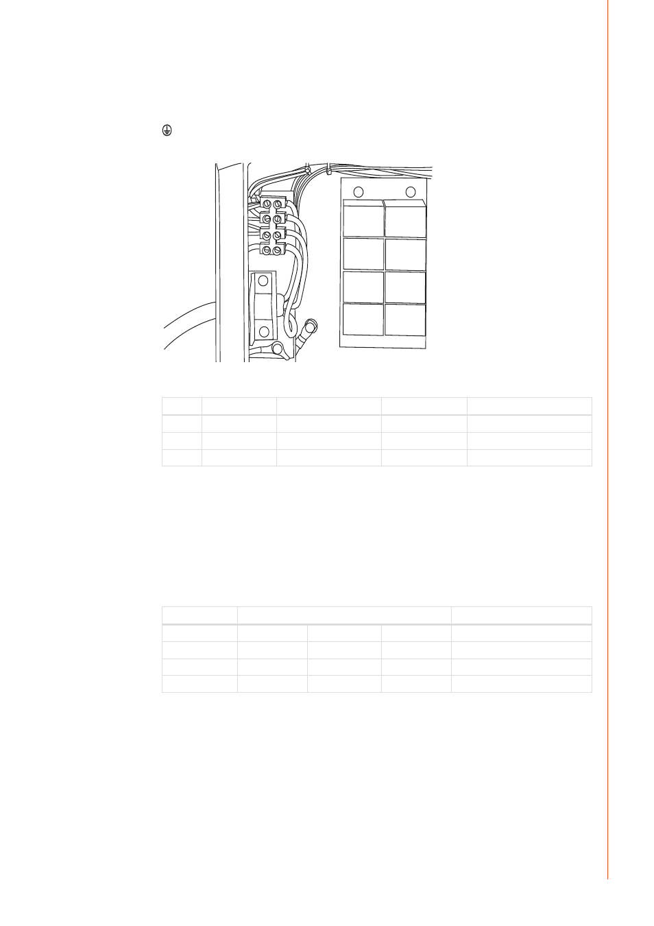
If changing the mains cable take into consideration the following:
The cable is entered into the machine through the inlet ring on the rear panel of the machine
and fastened with a cable clamp (05). The phase conductors of the cable are coupled to
connectors L1, L2 and L3. The earth protection coloured green-yellow is coupled to connector.
NOTE!
If you are using 5-lead cable, do not connect neutral conductor.
Sizes of the mains cables and fuse ratings for the machine at 100 % duty cycle are specified in
the table below:
Rated voltage
Mains voltage range
Fuses, slow-blow
Connection cable *) mm²
KMS 300 400 V 3~
360 V – 440 V
20 A
4 x 6.0 S
KMS 400 400 V 3~
360 V – 440 V
25 A
4 x 6.0 S
KMS 500 400 V 3~
360 V – 440 V
35 A
4 x 6.0 S
*) In cables of S type there is a protective grounding conductor coloured green-yellow.
2.4 Welding and earth cables
Recommended copper cables with cross-sectional area are as follows:
FastMig KMS 300 50 – 70 mm²
FastMig KMS 400 70 – 90 mm²
FastMig KMS 500 70 – 90 mm²
In enclosed table are shown typical load capacities of rubber insulated copper cables, when
ambient temperature is 25 °C and lead temperature is 85 °C.
Cable
Duty cycle ED
Voltage loss / 10 m
100 %
60 %
30 %
50 mm²
285 A
370 A
520 A
0.35 V / 100 A
70 mm²
355 A
460 A
650 A
0.25 V / 100 A
95 mm²
430 A
560 A
790 A
0.18 V / 100 A
Do not overload welding cables due to voltage losses and heating.
Fasten the earth clamp of the return current cable carefully, preferably direct onto the piece to
be welded. The contact surface of the earth clamp should always be as large as possible.
Clean the fastening surface from paint and rust.
7
© Kemppi Oy / 1515