Electrical connections, See all sub-paragraphs under 2.3, 3 electrical connections – Datalogic Scanning DS4600A User Manual
Page 19
INSTALLATION
2
2.3 ELECTRICAL
CONNECTIONS
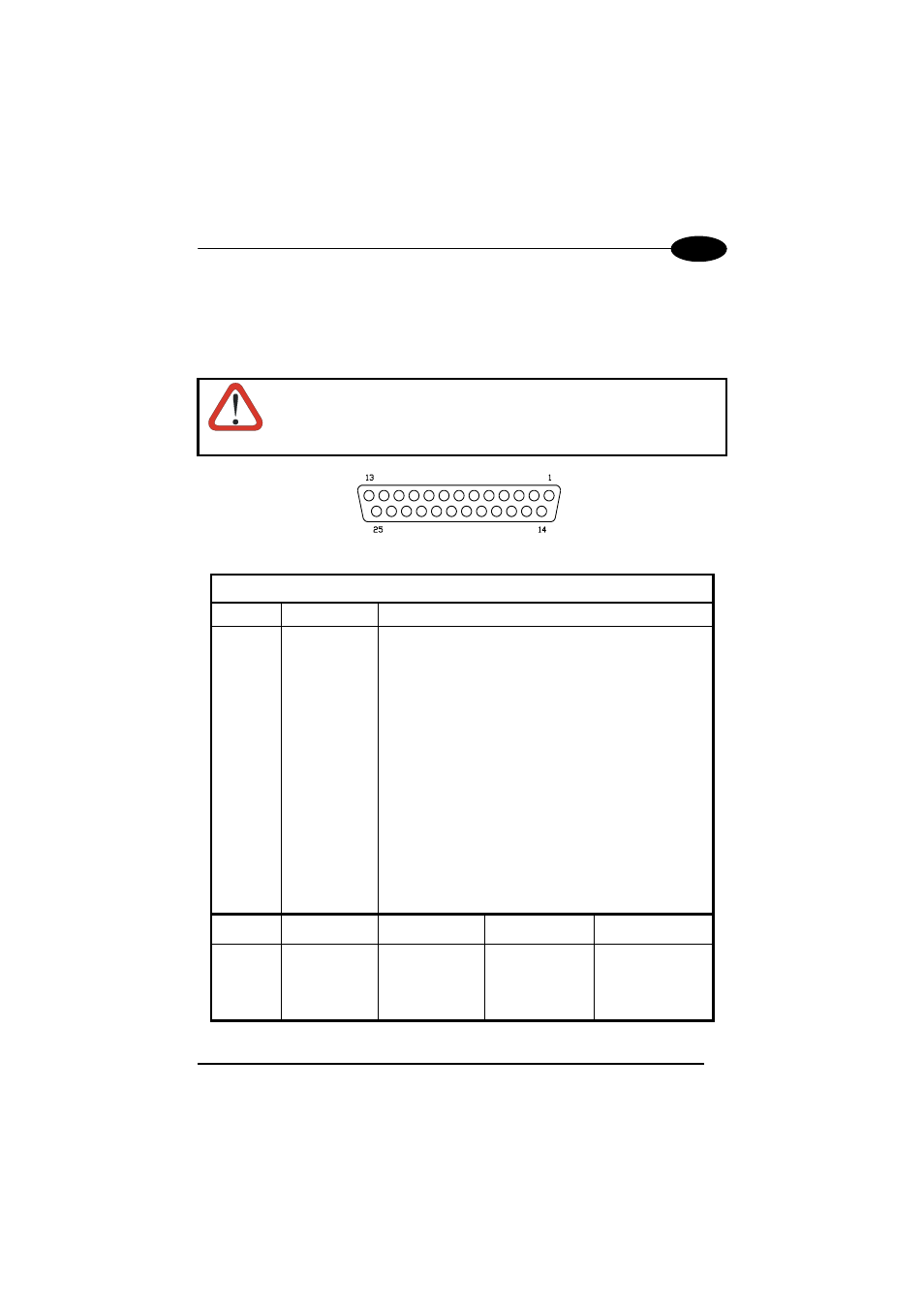
DS4600A is equipped with a cable terminated by a 25-pin D-sub connector for
connection to the power supply and input/output signals. The details of the connector
pins are indicated in the following table:
CAUTION
Do not connect GND and SGNDs (Main or Aux) to different
(external) ground references. GND and SGNDs (Main and Aux) are
internally connected through filtering circuitry which can be
permanently damaged if subjected to voltage drops over 0.8 Vdc.
Figure 5 - 25-pin D-sub Connector
25-pin D-sub connector pinout
Pin Name
Function
13
VS
Power supply input voltage +
25
GND
Power supply input voltage -
1 CHASSIS Chassis
Ground
9
VS
External Trigger supply voltage +
18
EXT TRIG+
External Trigger +
19
EXT TRIG-
External Trigger -
6
IN1 +
Input 1 +
10
IN1 -
Input 1 -
14
IN2 +
Input 2 +
15
IN2 -
Input 2 -
8
OUT1 +
Output 1 +
22
OUT1 -
Output 1 -
11
OUT2 +
Output 2 +
12
OUT2 -
Output 2 -
20
RXAUX
Auxiliary RS232 input
21
TXAUX
Auxiliary RS232 output
23
SGND Aux
Signal Ground Auxiliary interface
24
GND
Power supply voltage -
16 Reserved
17 Reserved
RS232 RS485
full-duplex
RS485
half-duplex
2
TX232
TX485+
RTX485+
3
Main interface RX232
RX485+
4
(see par. 2.3.2) RTS232
TX485-
RTX485-
5
CTS232
RX485-
7
SGND Main
SGND Main
SGND Main
7