Installation instructions, Electrical connection gas connection – ilve Freestanding Cookers User Manual
Page 36
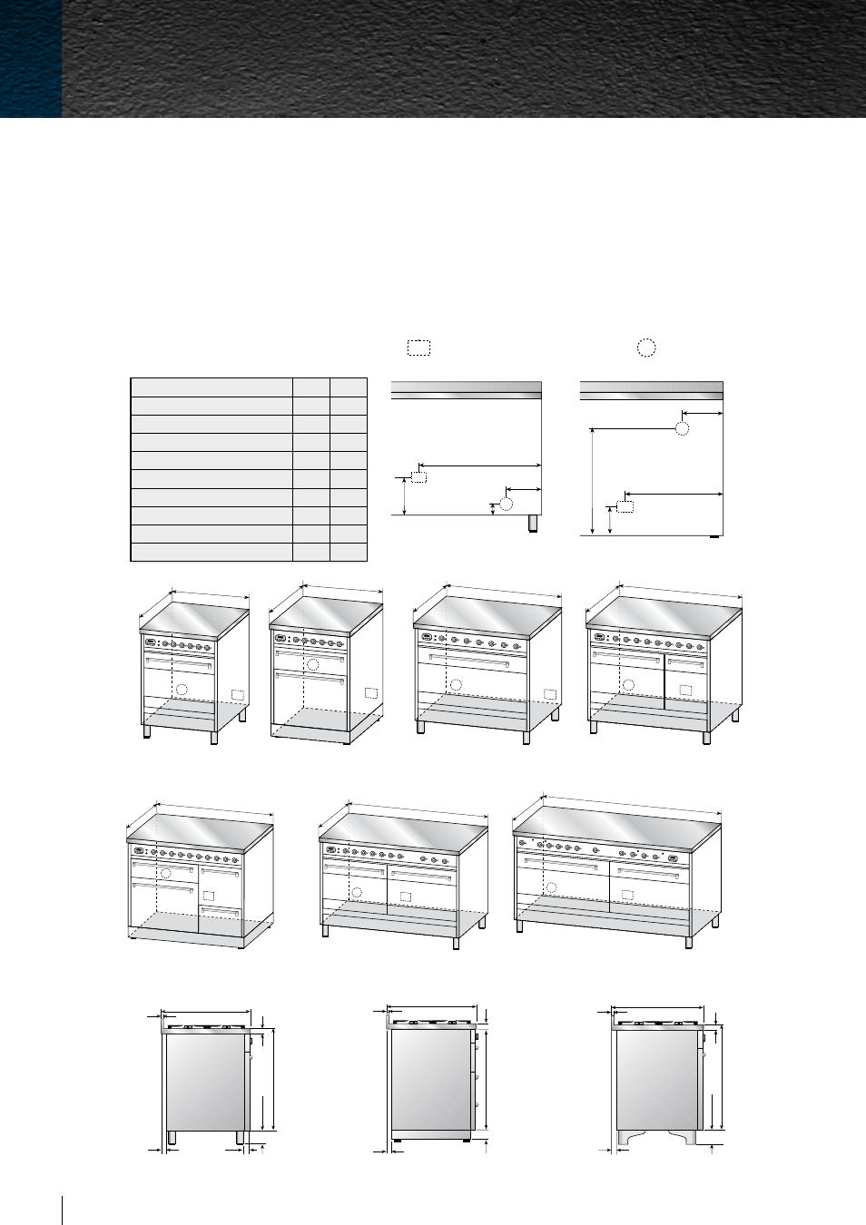
ELECTRICAL CONNECTION
GAS CONNECTION
GENERAL
1. The requirements of local Gas and Electrical authorities must be adhered to, Consult ASNZS 5601 and
SAA Wiring Rules as appropriate
2. Location of gas connection (See table)
3. Electrical connection (See Table)
4. Overall dimensions of hotplate Refer to dimensions chart in following pages
5. Eurolinx Pty Ltd and their appointed agents decline any responsibilities in the case of installation not
according to these instructions.
G
E
A
B
230
90
G
E
760 (P76) - 800 (P80) - 900 (P90
)
600
G
E
600 (P-60) - 700 (P-70)
600
G
E
1500 (P150) - 1200 (P120)
600
G
E
1200
600
G
E
900 (PD90) - 1000 (PD100)
600
G
E
700
600
E
G
1000 (PT100) - 1100 (PT110)
600
G
E
A
B
190
580
750
40
100
√
160
35
15
600
45
40
35
104
746
15
600
750
40
35
145
√
150
15
600
Model/mm
A
B
P60/PD120/QDC120
480
160
P70
530
220
PD70
530
240
P76
600
180
P80
680
200
P90/P120/P150
750
200
PD90/PD100/QDC90/QDC100 480
200
PT100
480
190
PT110
530
250
G
E
A
B
230
90
G
E
A
B
230
90
Rear View
Rear View PD70-PT100-PT110
P60-P70
PD70
PD90-QDC90-PD100-QDC100
P76-P80-P90
PT100-PT110
P120-P150
PD120-QDC120
Side View
Side View QDC (Classic)
Side View PD70-PT100-PT110
installation instructions
freest
anding cookers
36
ILVE Freestanding Operating Manual