J12: usb2/usb3 connector, J13: lcd backlight connector (dc type), J15: hdd power connector – IBASE IB886 User Manual
Page 22: J16: dc-in 12v power connector, J17: system function connector, Power led: pins 3 and 4
INSTALLATIONS
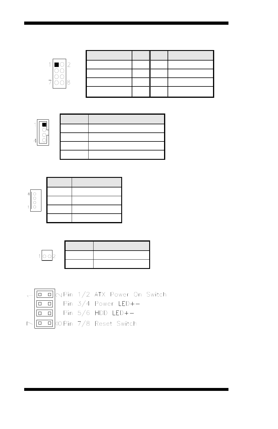
J12: USB2/USB3 Connector
Signal Name
Pin
Pin Signal Name
Vcc 1
2
Ground
D0- 3
4 D1+
D0+ 5
6 D1-
Ground 7
8 Vcc
J13: LCD Backlight Connector (DC type)
Pin #
Signal Name
1 +12V
2 Backlight
Enable
3
*Backlight Adj (DC type)
4
Ground
J15: HDD Power Connector
Pin #
Signal Name
1 +5V
2 Ground
3 Ground
4 +12V
J16: DC-IN 12V Power Connector
Pin #
Signal Name
1
DC in (12V only)
2 Ground
J17: System Function Connector
ATX Power ON Switch: Pins 1 and 2
This 2-pin connector is an “ATX Power Supply On/Off Switch” on the
system that connects to the power switch on the case. When pressed, the
power switch will force the system to power on. When pressed again, it
will force the system to power off.
Power LED: Pins 3 and 4
18
IB886 User’s Manual