Quick reference to cable / hose dimensions – Hypertherm HD3070 w/ Automatic Gas User Manual
Page 33
2-8
HD3070 w/Automatic Gas Console
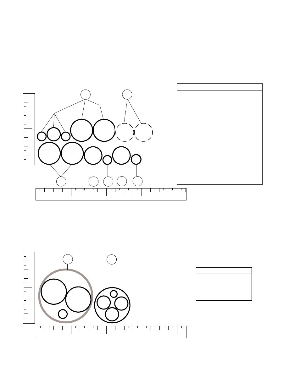
QUICK REFERENCE TO CABLE / HOSE DIMENSIONS
Figure 2-5 Cables / Hoses in Machine Cable/Hose Carrier
12
1-1/2 in.
HD3070 System - (Ref. Fig. 1-10)
The following figures are a one-to-one representation of the HD3070 system interconnecting
cables and hoses. Figure 2-4 shows cables and hoses that would lay in the rail at the site. Figure
2-5 shows cables and hoses that would lay in the cutting machine's cable/hose carrier. The rulers
have been added to use as a guide. Arrangement of cables and hoses laying in rails or carriers are
roughly suggested here.
5/8 in.
Figure 2-4 Cables / Hoses in Rail
1
2
3
4
Key - Figure 2-5
13 Shielded Torch Leads -
RHF Console to Torch
17 Leads -
Gas Console to Off-Valve
1/4 in.
3/8 in.
4
6
1/4 in.
Key - Figure 2-4
4 Leads - Power Supply to RHF Console
1/4 in.
Pilot Arc Lead
3/8 in.
Negative Lead
1/4 in.
Control Cable
5/8 in.
Coolant Supply Hose
5/8 in.
Coolant Return Hose
6 Leads - Power Supply to Gas Console
(only if gas console is not attached to
power supply)
1/2 in.
Cable - 3X2 Control
1/2 in.
Cable - 3X1 Control
A Hoses - Gas Supply to Gas Console
18 Cable, - Gas Console to Machine Interface
19 Cable, Control - Power Supply to
Machine Interface
20 Cable, Curr. Setpoint - Power Supply to
Machine Interface
21 Cable, Tmr-Cntr - Power Supply to
Machine Interface
12
1
2
3
4
1/2 in.
1/4 in.
5/8 in.
5/8 in.
5/8 in.
1/2 in.
1/2 in.
1/2 in.
5/16 in.
A
19 20 18 21
13
17
1-00