Herrmidifier Drain Tempering Reservoir User Manual
Page 5
Drain Tempering Reservoir
I n s t a l l a t i o n , O p e r a t i o n , & M a i n t e n a n c e M a n u a l
5
www.herrmidifier-hvac.com
the main water supply.
• Ensure that adequate pressure (25 psi minimum)
will be supplied to the Drain Tempering Reservoir.
Do not use water lines that are dedicated to other
appliances.
• Do not branch off of the water supply line that feeds
the humidifier.
• Install a cold water shut off valve before the service
union in the supply line.
7. Hot Water Inlet Connection:
• The hot water inlet connection is 1” male pipe thread.
• Run a 1” pipe as directly as possible to the reservoir
hot water inlet. If the piping is coming from a
horizontal run, ensure that adequate pitch to the
Drain Tempering Reservoir is at least 1% (1/8” per
foot).
8. Tempered Water Drain Outlet:
• The tempered water drain outlet is 2” male pipe
thread.
• Run a 2” pipe as directly as possible from the Drain
Tempering Reservoir to the drain. Ensure that
adequate pitch to the drain is at least 1% (1/8” per
foot).
• Make sure to leave a 1” air gap between the drain
piping and the drain.
• Once installed, simply open the cold water shut
off valve. The Drain Tempering Reservoir will
temper the drain water whenever hot water from
the humidifier enters the reservoir. No electrical
connections are necessary.
VI. ADJUSTING THE TEMPERATURE ACTUATED VALVE:
Using a thermometer to measure the tempered water
discharging from the unit, turn the adjusting screw to raise
or lower the temperature. Raising the valve opening point
will increase the tempered water temperature. Lowering
the valve opening point will decrease the tempered water
temperature. To raise the valve opening point on direct-
acting valves, turn the adjusting screw counterclockwise. To
lower the valve opening point, turn the range adjusting screw
clockwise..
.
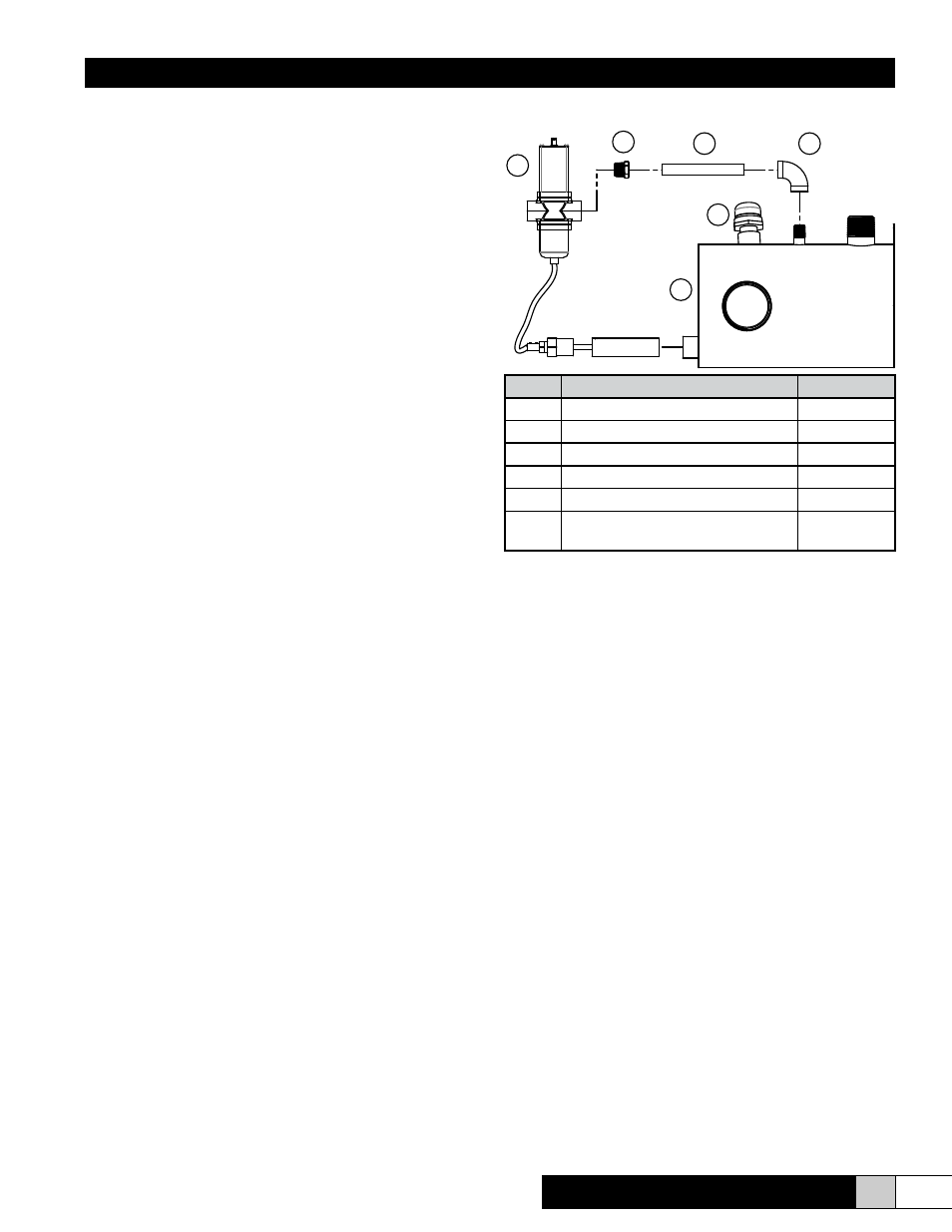
VII. REPLACEMENT PARTS:
.
3
4
5
6
2
1
Item
Description
Part Number
1
Drain Tempering Tank Welded Ass’y 266514-001
2
Vacuum Relief Valve
166524-001
3
Pipe Elbow, Brass (1/4”)
266207-001
4
Nipple, Schedule 40, 1/4” MPT
AH-166-4
5
Reducing Bushing, 1/4” To 3/8”
143903-004
6
Temperature Actuated Mounting
Valve
266534-001